Create/Edit Primitives
Create, Edit and Assign Primitives
Use the Create/Edit Primitives option to create and edit primitives, as well as apply them to nominated objects.
Primitives are useful when repeatedly using complex 3D designs where the shape is always basically the same. Instead of redesigning the object every time it is needed, it can be designated as a primitive and applied to any line. For example, when designing a tunnel you could create a line and then apply an arch shaped primitive.
Primitives are stored in the Primitives specification file ( <proj>.pgd ). See Appendix A for an example.
The Create/Edit Primitives option uses the Primitives GUI ( G raphical U ser I nterface). This new interface combines the functionality that was originally provided through the Primitive option (under the Design > Create submenu), the Apply Primitive option (under the Design > Attribute Edit submenu), and the Primitive option (under the Model > Triangle Solid submenu) in earlier versions of Vulcan.
Instructions
On the Model menu, point to Primitives, and then click Create/Edit Primitives to display the Primitives panel.
Primitives
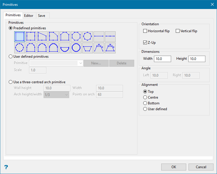
Located at the top of this section is a collection of predefined geometric shapes. To use a shape as a primitive, select the appropriate image.
Figure 1 : Predefined Shapes
User defined primitives
Enter the name for the new primitive (a maximum of 10 alphanumeric characters). Primitive names cannot contain spaces.
If you have entered the name of an already existing Primitives specification file (.pgd), then you will be prompted as to whether you want to overwrite it.
Scale
Enter the factor by which the primitive will be enlarged or reduced when it is applied to each line segment or interval.
Click New to open the primitive editor.
Use a three-centred arch primitive
Select this option to use a three-centred arch primitive. The arch consists of three intersecting arcs with three different centres respectively, and therefore called three-centred arch.
You will need to specify the wall height, roadway width, and arch height/width, as well as the points on arch. The points on arch (between 2–63) refers to the number of points that will be created on the arch. The arch height is generally 1/3, 1/4, or 1/5 of the width of the roadway. According to this, the formula for r and R is shown in the table below:
|
AH = 1/3 * W |
AH = 1/4 * W |
AH = 1/5 * W |
|
|
r |
0.691898 * W |
0.904509 * W |
1.128887 * W |
|
R |
0.260957 * W |
0.172746 * W |
0.128445 * W |

Figure 2 : Cross section of three-centred arch
Orientation
Horizontal flip
Select this check box to reverse the primitive along its horizontal axis, i.e. turn it upside down.
Vertical flip
Select this check box to reverse the primitive along its vertical axis, i.e. make a mirror image.
Dimensions and Angle
This section allows you to specify the height and width of the chosen primitive.
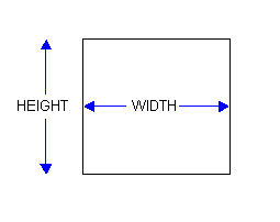
Figure 3 : Dimensions
In the case of the primitives located on the far right of the second row, you can also specify the left and right angles.
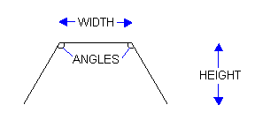
Figure 4 : Angles
Alignment
This section allows you to indicate the alignment line. This refers to the position where the primitive will be applied. The position (when viewed through the Editor tab) will be marked with a red dot.
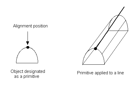
Figure 5 : Top Alignment
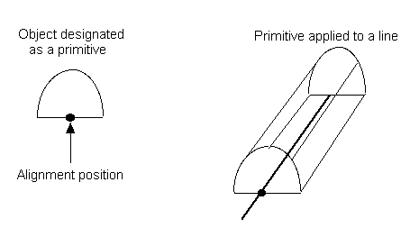
Figure 6 : Bottom Alignment
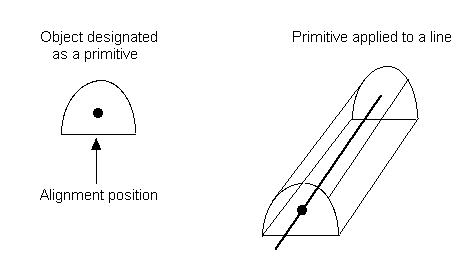
Figure 7 : Centre Alignment
Select the User defined option to specifically define the alignment for the chosen primitive. Once selected, you will need to open the Editor window (through selecting the Editor tab). Once the Editor window has been opened, use the Indicate Origin button to indicate the alignment position.
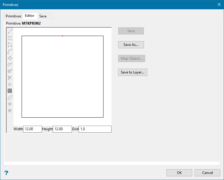
Editor tab
| Primitive Editor toolbar | ||
|---|---|---|
| Icon | Tooltip | Description |
|
|
Draw line |
Allows you to create a line. Steps:
|
|
|
Draw polygon |
Allows you to create a polygon. Steps:
|
|
|
Draw arc |
Allows you to design a circle or arc. Steps:
|
|
|
Draw arc |
Allows you to design an arc. Steps:
|
|
|
Move point |
Allows you to move a point to a new position. Steps:
|
|
|
Delete object |
Allows you to delete an object. Steps:
|
|
|
Delete point |
Allows you to remove individual points from an object. Steps:
|
|
|
Delete all |
Allows you to delete all objects displayed in the Editor window. Steps:
|
|
|
Indicate origin |
Allows you to indicate the alignment line for the primitive. |
|
|
Toggle grid |
Allows you to toggle grid display, that is show or hide. |
|
|
Select object |
Allows you to select objects from in the Editor window. This button needs to be selected prior to using the editing tools, i.e. the |


Width
Enter the width of the Editor window.
Height
Enter the height of the Editor window.
Grid
Enter the size for the grid squares.
Save
Use this button to save the changes made to an existing primitive. If this button is selected when saving a new primitive, then the Primitive Name panel displays. Refer to the information below for details on this panel.
Save As
Use this button to save the chosen shape as a new primitive. Once selected, the Primitive Name panel displays.
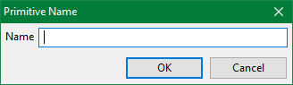
Enter the name for the new primitive (a maximum of 10 alphanumeric characters).
Click OK to save the primitive. You are then returned to the Primitives interface. The primitive will be saved to the Primitives specification file ( .pgd ), as well as displayed under the User Primitives section.
Map Object
Use this button to map an existing Vulcan design object to the Editor window. Once selected, you will be prompted to pick the object from the screen. The chosen object will then be displayed in the Editor window.
Save to layer
Users can also export primitives to objects in a design database (dgd.isis) for plotting on cross sections. The primitives could be predefined, original, or user created ones.
Choose a primitive to export and click this button to open the Export profile to design database panel.
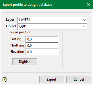
Layer
Select an existing layer from the drop-down list or simply type in a new layer name. Selecting an existing layer overwrites the previous data.
Object
Select an object from the drop-down list if a pre-exisitng layer is selected or simply type in a new object name. Selecting an existing object overwrites the previous data.
Original position
Enter the values for the locating the original position or choose to select the origin point from the screen by clicking Digitise button.
Click Export to export the chosen primitive to the object in design database.
Save tab
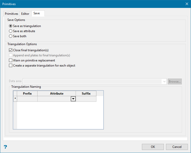
Save Options
Specify whether the primitive is to be saved as a triangulation, an attribute, or both. The Save Triangulation panel displays when using the Save as Triangulation and Save both options.
The following options are only available when saving the primitive as a triangulation, or when saving the primitive as both a triangulation and an attribute:
Triangulation Options
Close final triangulation(s)
Select this check box to close the triangulations. This check box will be selected by default.
Append end plates to final triangulation(s)
Select this option to add end plates to the final triangulations. The triangulation will not close, which results in a surface suitable for Boolean operations such as Open Pit > Open Cut Design > Pit Topography. This option is only available if the Close final triangulation(s) check box is cleared.
Warn on primitive replacement
Select this check box to be warned whenever an existing triangulation/primitive is about to be replaced.
Enabling this check box will result in a prompt being displayed informing you of the possible replacement. You will need to confirm your selection in order to continue.
Create separate triangulation for each object
Select this check box to create a separate triangulation for each of the selected objects.
Data area
Select the directory that will be used to store the resulting triangulations. Leave this field blank if you want to save the resulting triangulations within your current working directory. Use the Browse button if you want to nominate a different storage location.
To save your triangulations within an existing triangulation database, use the Browse button to locate the applicable.tri file. Once found, click on the file before clicking OK.
If you want to store the triangulations within a subdirectory of your triangulation database, double-click on the.tri file to display the Select Directory panel.
Once you have located the desired storage folder, click on the folder name before clicking OK.
Triangulation Naming
The triangulations can be named with various combinations of layer, feature and group.
If the values shown above were used, then the triangulation will be named:
ef<feature_name>ghij<group_name>klmn<object_name>op.00t
If the values shown above were used, then the triangulation will be named:
a<layer_name>bc<feature_name>de<group_name>fg<object_name>h.00t

