Macro File Commands
The macro file for block projections is created through the Create Macro option (under Benching and Batters). The format of the file name is <name>.proj.
The file contains operational and instructional commands. Operational commands perform an operation on a block, while instructional commands control how the projection is to be performed.
The operational commands that can be generated through the Create Macro option are:
BERM
COPY
PROJECT
REGISTER
UPDATE_BLOCK
The instructional commands that can be generated through the Create Macro option are:
CONDITION_LINE
CONNECT_CORNER
LIMIT
RESERVE_BLOCK
RESTORE_BLOCK
SAVE_WTAGS
SET_BLOCK
STRAIGHT_FACE
UNSET_BLOCK
INITIAL
Other commands that may be used, but are not automatically generated, can be added through the Edit Macro option. The Edit Macro option can also be used to add qualifiers to the commands.
Note: I nstructional commands should be issued BEFORE any operational commands. Commands and qualifiers are not case sensitive, that is, you can use uppercase, lowercase or a combination.
An overview of the available commands and qualifiers is given on the next pages followed by some notes on horizontal projections.
Instructional Commands
Operational Commands
Notes - Horizontal Projections
| Instructional Command | Description |
|---|---|
| CONDITION_LINE |
This performs the same function as the Condition string option under Open Cut Design. The option can be used to insert extra points in a line, to filter out points too close together, and to remove points that form small angles. It is especially useful to rectify errors that may occur with the berming commands (see Operational Commands). The CONDITION_LINE command has the following qualifiers:
/DIST_MIN=n.n
/DIST_MAX=n.n
/ANGLE_MIN=n.n
/ANGLE_MAX=n.n
|
| CONNECT_CORNER | This specifies that lines be drawn connecting the corners of the blocks. This is only effective if STRAIGHT_FACE has been specified. The lines that are created are only for appearance sake for aiding the viewing of a projected block. They have no effect on subsequent volumes calculations. The lines are created as objects in the same layer as the block, and have a common feature name, which means they can be deleted by the feature category in Object Edit/Delete. |
| LIMIT |
Specifies the topography surface. It has the following qualifiers:
/SURFACE
= 'aaa'
/STOP_AT_LIMIT
|
| PRESERVE_BLOCK | Stores the current block coordinates for later restoration (see RESTORE_BLOCK). It to perform a complex set of projections and store the result for later use in the macro. Unlike SET_BLOCK, PRESERVE_BLOCK allows a physical projection location to be saved. |
| RESTORE_BLOCK | Replaces the coordinates of the current block with those set by the previous PRESERVE_BLOCK. This then becomes the current block. It does not alter the name of the current block. |
| SAVE_WTAGS |
Replaces the default W-tag values with those that reflect the macro command that is about to be processed. For example: If an object is to be bermed next, then it will set each segment of the object that is about to be bermed with the berm distance as defined for that part of the object in the macro. Note This is an optional command. Using this command can slow down a large run. |
| SET_BLOCKS |
This to position a block via a set of operational commands. Once this command is issued any operational commands will not create new objects, but will move the current object. In general the projection sequence is either from the lowest surface upwards or from the top surface downwards, and the original 2D block is referenced to the lowest or highest surface respectively. However it may be required that the 2D block is referenced to another surface. By using SET_BLOCKS, a series of operational commands can be given to move the block to the upper or lower surface, then once the block is in position an UNSET_BLOCKS command is given so that the following operational commands will project the block. |
| STRAIGHT_FACE |
This specifies that the projection be done such that the face
for each block remains straight in plan. This has the effect that
the specified batter for the face may vary along the length of
the face.
If this command is not given, the projection assumes that the batters will remain constant along the block face, which means that the projected face line may possibly be not a straight line, depending on the geological structure. |
| UNSET_BLOCKS | This turns off the set blocks so that any following operational commands will continue to create new objects. |
| INITIAL |
This set the starting block number. If not set, the first block
will be used. The INITIAL command has the following qualifier:
/BLOCK_NUM=nn |
|
Operational Command |
Description |
|
BERM |
Takes the current block and berms all the points on it horizontally, subject to qualifiers specified below overriding this. The qualifiers are:
/SURFACE
= 'aaa'
/HORIZONTAL
/ALONG
/UP
/DOWN
/WIDTH
= n.nnn,
If a list of berms is specified, then each width is associated with the corresponding wall in the /WALL qualifier.
/WALL
/COLOUR
/DEFAULT
|
|
COPY |
This copies the current string in the macro sequence. This is useful when your original block is already registered to a surface instead of the typically designed 2D blocks. Copying the original string allows that string to be included in the set of projected strings. Registering the original string may slightly change the string, so the Copy command provides a better way to include the original string. The Copy command has the following qualifiers:
/SURFACE='aaa'
/CREST
/COLOUR
|
|
PROJECT |
This takes the current block and projects it. It has the following qualifiers:
/LEVEL
= nn.nnn
/SURFACE
= 'aaaa'
/RELATIVE
= nn.nnn
/UP
/DOWN Project the block downwards. This is necessary if projecting down through surfaces, from the upper surface to the lowest. This is not necessary, if only using levels or relative distances. /FORCE (see below) should also be used to ensure that the wall angles are taken into account while projecting when using the /DOWN command.
/HORIZONTAL
/BATTER
= nn.nnn
Batter angles are in degrees from the horizontal, hence a vertical batter is 90 degrees. If a list of batters angles is specified then each angle is associated with the corresponding wall in the
/WALL
qualifier.
FACE
Matches to all face
walls
Matches to current,
or leading face
Matches to next, or
trailing face
Matches to all side
walls
Matches to left side
wall
Matches to right side
wall
Matches to all end walls
Matches to left end
wall
Matches to right end
wall
A special wall type,
number 1
A special wall type, number 2
/COLOUR
/FORCE
/INTERP
/OFFSET
|
|
REGISTER |
This registers a block to a surface. This normally the first operational command issued. For example if we are projecting upwards then we would register our original 2D mine block to the lowest seam. If we are projecting downwards, we register to the highest seam, usually the natural surface. The register command makes a new block (object) rather than registering the original mine block itself (compare with Object Edit/Register option).This has the following qualifiers:
/SURFACE
= 'aaa'
/INTERPOLATE extra points along the block face so that it follows the surface more closely. Otherwise only the corner points are registered. /COLOUR Sets the colour for the above surface. |
|
UPDATE_BLOCK |
Similar to RESTORE_BLOCK with the addition that the name of the block is changed to the current macro level. Note that all blocks are named according to the current macro level. |
Notes - Horizontal
Projections
The following are notes to assist in projecting horizontally through steeply dipping structures.
In a simple case of one seam, we can use the following commands in the macro projection file:
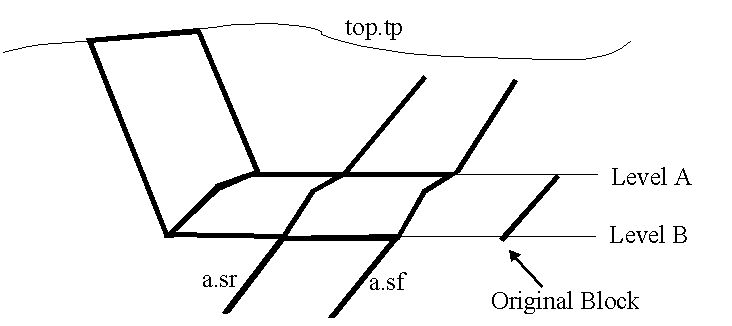
PROJECT/HORIZONTAL/SURFACE='A.SFG'/INTERPOLATE
PROJECT/HORIZONTAL/SURFACE='A.SRG'
PROJECT/HORIZONTAL/level=-50
PROJECT/SURFACE='TOP.TPG'/BATTER=(35.0, 90.0, 90.0)/WALL = ('FACE','SIDE','END')COLOUR=5
In section this will look like this:

Diagram 1 - Section Showing Projection
From the original block which is placed to the right, below the seam, the projection is done to the floor of the seam, and interpolated along the seam. In effect this is the same as a normal registration, except it is done horizontally instead of vertically. On the first projection, we normally interpolate extra points onto the grid. It then does a registration to the roof of the seam without interpolation.
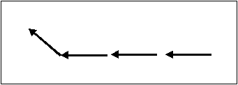
For illustration, we then do a 50m relative projection from the roof. This gives us a working surface between the highwall and the coal. The projection to the topography is then done as normal. Diagram 2 shows the sequence of the projection.

Diagram 2 - Direction of Projection
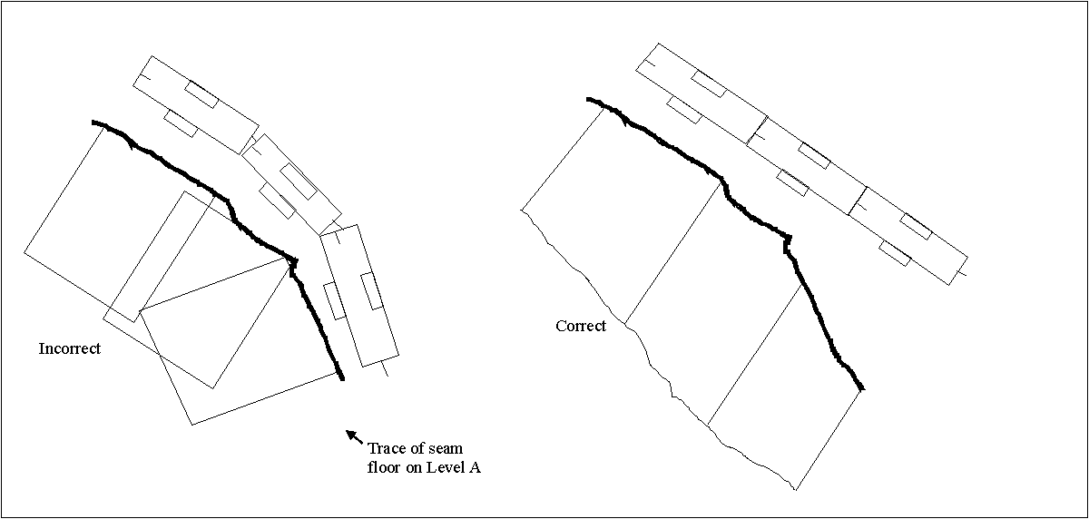
The direction at which the projection is done depends on the orientation of the face walls on the original blocks. See Diagram 3.

Diagram 3 - Incorrect and Correct Method of Laying Out Blocks
From this it is important that when laying out the blocks, that they all are in a straight line. If they are following the seam, then the projections will overlap and the volumes will be incorrect.
The original block design itself is important. In the normal projections, the blocks can be at any elevation. With the horizontal projection, the blocks must be designed at the level on which you want the bench. See Diagram 4.

Diagram 4 - Original Block in Plan and 3D
Thus the two face walls of the block lie on two different elevations. This is currently a very manual step.
Also, the horizontal projection works only in a limited number of cases in terms of structure of the seams. For faulted or basin structures the method may fail. This is true even if the structure is masked out, as the projection in all cases ignore the masks on grids. Diagram 5 gives examples of structures in section where the projection will fail.

Diagram 5 - Examples of Projection Failures

