Bench Volumes
Reporting cut and fill volumes between mine designs
Use the Bench Volumes option to calculate the cut and fill volumes (volume changes) between two open-cut mine designs (For example, date 1 and date 2) on a bench by bench basis and optionally subdividing by polygon in each bench. The data generated through this option can be outputted to either a CSV or a Vulcan dump file (
.dmp
).
Specifications from previous runs can be saved and reused. If you have used this option previously and saved your specifications, then you can use the Specification file option to reuse these specifications.
It is also possible to run this option using the tribench executable.
Instructions
On the Open Pit menu click Bench Volumes to display the following panel.
Specification file
Specification file
Use the drop-down list to select the specification file if it is in the current working directory, or browse for it in another location by clicking the Browse icon. A new file may also be created by typing the name of the new file in the textbox and clicking the New icon.
-
 Browse
 -
 New
New -
 Save
Save -
 Save as
Note: The specification file (*.tb_spec) is used to store the parameters used in bench volume calculation.
The Bench Volume Calculation panel also consists of the following tabbed panels:
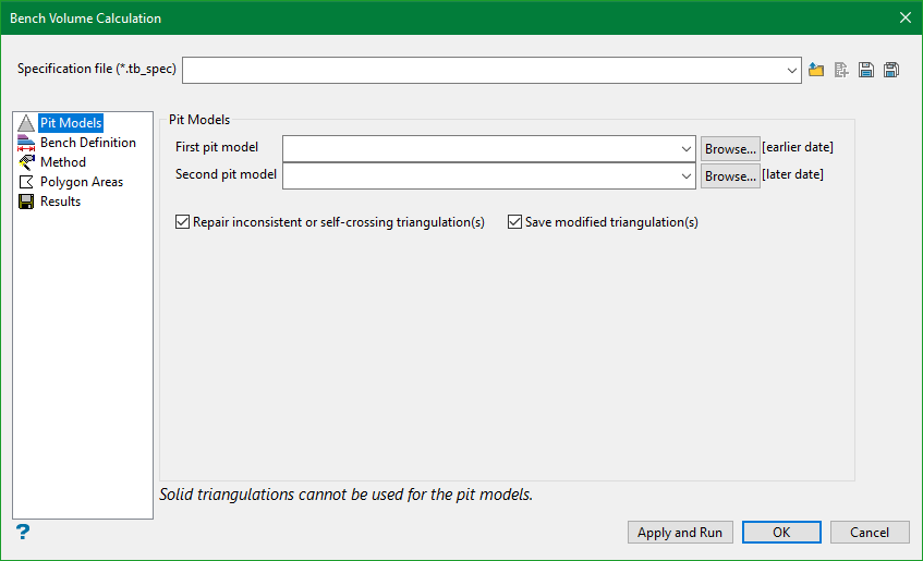
Pit Models
First pit model
Of the two pit models this should be the earlier dated model. The list contains all triangulations in the current working directory. Click Browse to select a file from another location.
To use a triangulation from an existing triangulation database, click Browse to locate the applicable triangulation database connection file (.tri). Once found, double-click on the file to display the Select Triangulation panel.
Click on the desired triangulation and then click OK.
Second pit model
Of the two pit models this is the later model. The list contains all triangulations in the current working directory. Click Browse to select a file from another location.
To use a triangulation from an existing triangulation database, click Browse to locate the applicable triangulation database connection file (.tri). Once found, double-click on the file to display the Select Triangulation panel.
Click on the desired triangulation and then click OK.
Note: When manually entering the names of the desired triangulation models, you will need to enter the full name including the file extension.
Do not use solid triangulations. If have you selected a solid triangulation as one of the pit models, then an error message displays informing you that the triangulation has no boundary and the option will be cancelled.
Repair inconsistent or self-crossing triangulation(s)
If this option is selected the faulty triangulation will be re-triangulated prior to bench volume calculations.
Save modified triangulation(s)
If this option is selected the re-triangulated result is saved in a form <faulty triangulation name>_modified.00t. The latter option is added for the purpose of giving user the means to review the repaired triangulation. Re-triangulation potentially can change the shape of the surface. The degree of permissible change is for user to decide.
Bench Definition
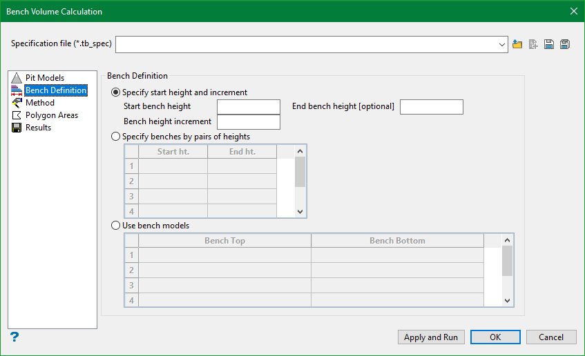
There are three methods for defining the benches.
-
Specify start height and increment
Select this option to enter the start height and increment of the benches. It is also possible to enter an end height. Omitting the end height will cause calculation to continue by increment to the full height extent of the pit models; the end height can be used to restrict the number of increments. Negative increment value may be used to work downwards (the end height must reflect the increment sense). Benches are defined as parallel horizontal planes at the height plus the increment. -
Specify benches by pairs of heights
Select this option to specify the benches in pairs giving the start and end height for each bench. These values can be specified in either order. Extra rows will be added to the table as you type beyond the last row. Benches are defined as parallel horizontal planes at the two heights. -
Use bench models
Select this option to use models of the benches. This option to use arbitrary shaped benches. Select the required model from the drop-down list that contains a list of models in the current directory or browse from other directories. Grid and/or triangulation models may be selected.
Select the models for both the bench top and bottom. Extra rows will be added to the table as you type beyond the last row. Benches are defined by those parts of the model that intersect with the pit models. Please note that no checking is made of the height order (top/bottom) of the models specified, for the extent of overlap, or for model crossing. As these checks are as computationally intensive as the volume difference calculations, they have been omitted. If the order is wrong (upside down), then the cut and fill volumes reported will be reversed.
Method
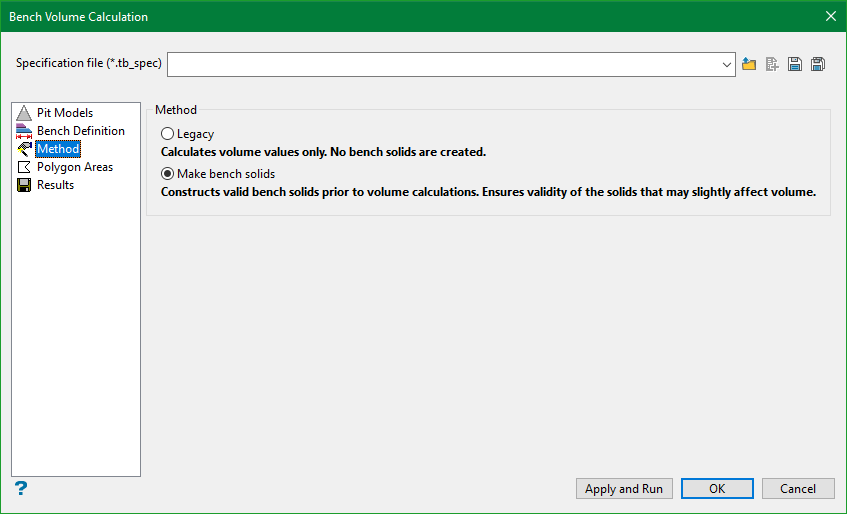
Sometimes, users may require just the numeric values of the bench volume without the need of having the bench solids created. Depending upon the requirement, there are two methods of calculating Bench Volume:
Legacy: The legacy method calculates only the values of bench volume. This method is relatively faster and could be used for assessment of bench volumes.
Make bench solids: This method not only calculates bench volume but also creates bench solids before the volume is calculated. This method is relatively slower than legacy method, particularly in case of large scans of nearly identical areas.
Polygon Areas
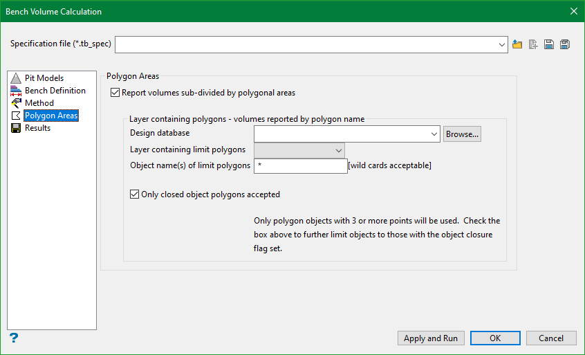
Report volumes sub-divided by polygonal areas
Select this option to subdivide further the volumes reported per bench into changes in polygonal areas.
You will need to enter, or select from the drop-down list, the Design Database and Layer in which the polygons are stored. You will also need to enter the object name, however, multi-character (*) and single character (?) wildcards are allowed.
Example:
If all objects in a layer are required, then enter *, if names
BLOCK001
to
BLOCK009
are required, then enter
BLOCK00*.
Only line/polygon objects will be used from this layer, other objects (i.e. text) will be ignored.
Note: When using Polygon Areas and Output data as a DMP file, you can have up to 40 characters in the Layer and object names.
Only closed object polygons accepted
Select this check box to limit the line objects further to be true polygons having the closed attribute set, that is, closed polygons.
Results
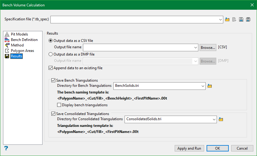
Output data as CSV file
Select this option to write the data to a CSV file. The drop-down list contains all CSV files found within your current working directory. Click Browse to select a file from another location.
To create a new file, enter the file name with the extension in the text field.
Output data as DMP file
Select this option to write the data to a nominated dump file (.dmp). The drop-down list contains all .dmp files found within your current working directory. Click Browse to select a file from another location.
To create a new file, enter the file name with the extension in the text field.
Note:
If you manually enter the file name, then you will need to add the '
.dmp
' file extension for it to be recognised as a DMP file.
Append data to an existing file
Select this check box to append the data to an existing file. If you select an existing file, and you do not check the Append data to an existing file check box, then you will be prompted to overwrite the chosen file.
Save Bench Triangulations
Select this option to save the resultant bench triangulation(s) to a directory. These benches follow the naming convention:
<Cut/Fill>_<BenchHeight>_<FirstPitName>.00t
Selecting the Display bench triangulations option will display the resultant bench solids on the screen.
Save Consolidated Triangulations
Select this option to save the consolidated bench triangulation(s) to a directory. These benches follow the naming convention:
<Cut/Fill>_<FirstPitName>.00t
Click Appy and Run to execute the Bench Volume calculation process. Clicking on OK will only save the settings to the specification file for future use.

