Automated Pit Designer
Modify Pit Design
This option allows you to modify an open pit design or dump that you have already created.
On the Open Pit menu, point to Automated Pit Design, then click Modify Pit Design.
Design pane
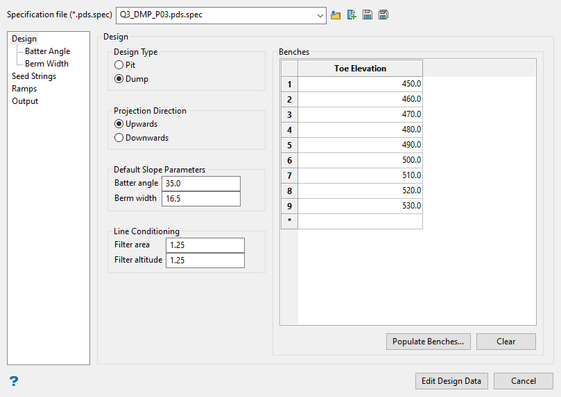
Design Type
Use this to select the design as either a pit or a dump. This determines how certain parameters will be utilized such as Rock/Void Access for a ramp.
Projection Direction
This sets which direction the design is being created in. A pit going upwards projects up and out where a dump going upwards projects in.
When the pit designer is constructing a design it will either progress upwards through the benches from the lowest elevation to the highest elevation, or downwards in the opposite direction. The process that the designer uses depends not only on the design direction, but also on the design type.
A PIT going UPWARDS corresponds to the design getting larger because the earlier strings will be contained within the later strings. This is analogues to a DUMP going DOWNWARDS. This case of the design is called OUT.
The opposite case is either a PIT going DOWNWARDS or a DUMP going UPWARDS, in which the later strings are contained within the earlier strings. This case is called IN.
| Design Type | Design Direction | Design Case |
|---|---|---|
| PIT | UPWARDS | OUT |
| PIT | DOWNWARDS | IN |
| DUMP | UPWARDS | IN |
| DUMP | DOWNWARDS | OUT |
Default Slope Parameters
Set the default batter angle and berm width for the design. This is used when no advanced parameters are supplied, or as a default when the advanced parameters do not cover a region.
Line Conditioning
Line conditioning works to remove small variations in projected toes and crests. It checks each triad of three points along the toe / crest for variances in area and altitude. If the area or the altitude are less than their respective cutoffs the middle point is removed. This reduces waves in the projected lines. However, the filtering will only remove points where the slope constraints are still satisfied.
Benches
This list determines which benches the designer will create and consider valid. Data not on these benches is ignored.
Populate Benches (button)
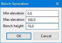
Enter the elevation of the lowest bench, the elevation of the highest bench, and the height of a single bench. Then click OK to populate the Benches table automatically.
Clear (button)
This will clear the Benches table of all values.
Batter Angle and Berm Width panes
These two panes are identical except that on one you will set the bearing angle for the batters, and the other you set the width for the berms.
Use Advanced Berm Angle Parameters
Select this option to enter detailed information about the berm angles. If this option is not selected, then the default value will be used.
There are three ways to set the parameters:
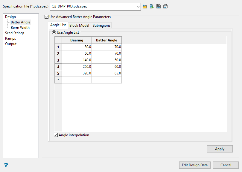
Angle List
One way to define the batter angle is with a single angle list. This angle list will apply to all locations.
Enter the Bearing for each Slope angle. At each bearing, the slope will be reproduced precisely. You can optionally apply linear interpolation between the angle by selecting the Angle Interpolation checkbox.
You can optionally apply linear interpolation between the angle by selecting the Angle Interpolation checkbox.
The angle list specified in the Angle List shown above is used for all bearings with and without linear interpolation.
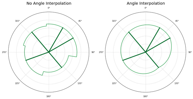
Figure 1 : Schematic for angle interpolation. Without angle interpolation the nearest bearing is used.
Block Model
Another way to supply the batter angles is from a block model.
First, specify the block model which contains the batter angle information from the drop-down list or browse to a block model in a different location.
This block model does not need to be the same as the pit number block model, it could even be a different size, which could improve computation time.
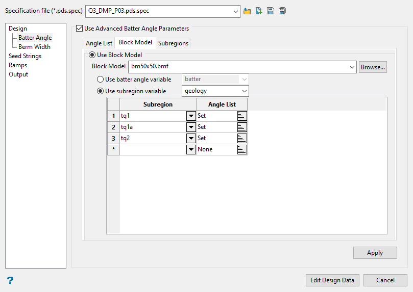
Once the block model is selected, there are two ways to supply the batter angle Information: batter angle variable or subregions variable.
Use batter angle variable
Use this option to supply the batter angle variable as a numeric block model variable. This quantity is entered in degrees.
Use subregions variable
Use this option to select an integer or name type subregion variable which specifies several subregions or domains.
If the subregion variable is a name type variable you may select the subregion from the drop-down menu. If the subregion variable is an integer type variable enter the value for each subregion in the Subregion column.
Then, use the rest of the grid to enter either the batter angle for each subregion or specify an angle list. An example angle list is shown below.
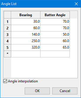
Figure 2 : Angle List Grid Panel with example input.
Enter the Bearing for each Slope angle. At each bearing the slope will be reproduced precisely.
Any subregions without an associated batter angle or angle list will revert to the default batter angle. Any inappropriate values (such as -99) will also revert to the default batter angle.
Note: If the polygons are not exclusive, the first subregion in the list will be preferred. That is, if zone02 and zone01 overlap in 2D space, then a point that is in both will use the angle list specified in zone01.
Subregions
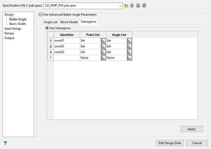
The final way to supply the batter angles is define the subregions individually.
Begin by naming the region with an identifier, then click the icon in the Point List column to display the Point List panel.
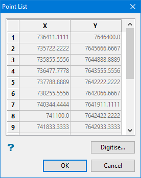
Each point location along the digitised line is recorded in the list.
Digitise (button)
Clicking this will allow you to draw a polygon that outlines the boundary of the region. The X and Y coordinates of each point along the string will automatically be listed in the table., or enter the coordinates individually, then click OK.
Next, click the icon in the Angle List column to display the Angle List panel, then set the bearing and batter angles for the region.
Click Apply.
Click OK to return to the main panel.
Seed String pane
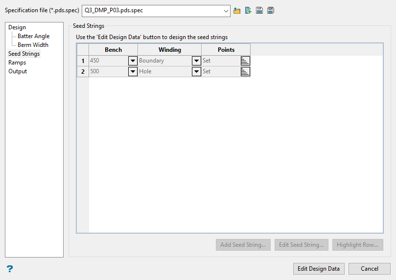
Note: To access the table on the Seed String pane, click Edit Design Data, then select Edit Seed String, Delete Seed String, and Seed String Details buttons to make changes to the seed string.
This will allow you to draw an initial polygon representing the pit floor or top surface boundary. After the boundary polygon has been created, the Auto Pit Designer will use it as the starting point for the pit or dump.
If, on the Design pane, you selected the projection direction to go upwards then the polygon drawn as the seed string will act as the pit bottom. If you selected the projection direction to go downwards, then the polygon will act as the top boundary to the pit.
Boundary strings and hole strings are incorporated differently. Boundary seed strings in a pit contain rock on the outside and void inside (similar to hole strings in a dump). Hole strings in a pit contain rock on the inside and void outside (similar to boundary strings in a dump). Hole strings must be placed inside boundary strings to have an effect on the model.
Ramps pane
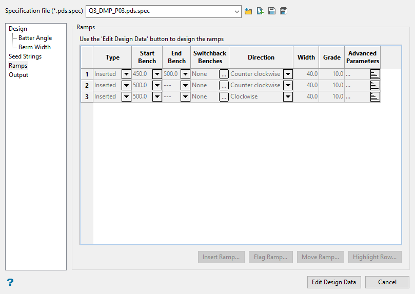
Note: To enable access to this panel, click the Edit Design Data button at the bottom of the main panel, then click Ramp Details.
Table
Type - Represents the ramp type, either Inserted or Flagged. Note that you can not change the width of a flagged ramp. Instead you have to change the segment it is flagged into. Also, you cannot change its direction. That is based on the angles before and after the segment.
Start Bench - Represents the first bench the ramp will appear on.
End Bench - Represents the last bench the ramp will be on.
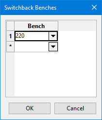
Switchback Benches - Click the small ellipsis icon to display the selection panel. Use this to select the bench(s) on which the switchback will occur.
Direction - Set the direction of the ramp.
Width - Set the width of the ramp.
Grade - Set the grade of the ramp.
Advanced Parameters - Rock access leaves the catch bench/berm open to the road versus narrowing out and cutting it off on each bench. It's the same for void berm access except that is into the pit out from the dump (away from whatever the material is).
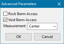
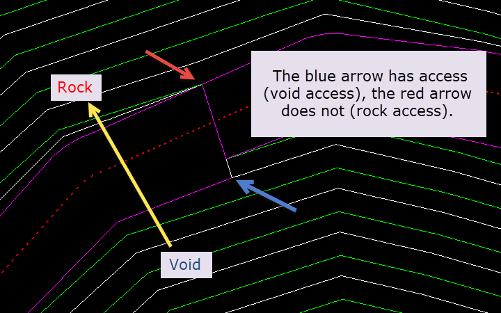
Figure 3 : In this image, the blue arrow has access (void access), the red arrow does not (rock access). The yellow arrow indicates the movement of the pit up, with the top being rock, bottom be void (into the pit).
The simplest way to create a ramp is from the Pit Designer toolbar menu. Click Insert Ramp, then select the starting point of the ramp anywhere along the seed sting.
However, if you want to have more control over the design, begin by designing the beginning of the ramp into the seed string, then apply a flag. Flag Ramp is for specifying a specific segment of the seed string to be the start of a ramp.
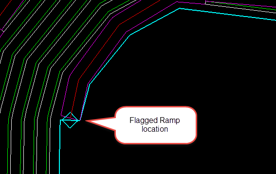
Figure 4 : Flagged ramp location.
The design will apply the width of the segment to the ramp.
Create a switchback on the ramp by clicking Flag Switchback, then selecting the elevation along the existing ramp that you want the switchback to occur.
Moving a flagged ramp directly is not recommended. Instead, redraw the seed string first with the Edit Seed String button. You will then have the diamond flag symbol floating in space but not attached to the seed sting. Then use the Move Ramp button to move the ramp flag to the new location.
Output pane
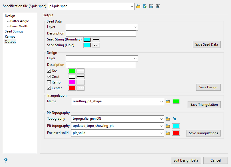
Layer
Specify the layer name to save the resulting design strings into, if left blank the name will be inferred from the spec file / scenario.
Description
Specify the layer description.
Saving the design
Toes, crests, ramps, and centrelines can be saved to a design layer. Select the appropriate checkboxes and specify the string colour using the colour box. Click Save Design.
Save Triangulation
Select this option if you wish to save the resulting pit design as triangulation. Specify the colour to be applied to the triangulation. Then click Save Triangulation.
Save Triangulations - Pit Topography
Topography - Select an existing topographic surface.
Pit topography - Enter a name for the new topographic surface that will be created by combining the existing topographic surface and the resulting pit design.
Enclosed solid - Enter a name for the resulting pit solid.

