Edit Macro
Edit Block Projection File
Use the Edit Macro option to edit an existing macro projection file.
Instructions
Select Open Pit menu, point to Benching and Batters, and then click Edit Macro to display the Select or key item panel.
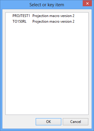
A list of available macros displays. From the list, nominate the macro that you want to edit.
Once selected, the chosen macro displays through the Benching and Batters Projection Macro panel.
P rojection Macro File
Projection macro file name
Enter the name of the macro projection file using up to 30 alphanumeric characters.
Description
Enter an optional description of the macro projection file.
Projection Macro Defaults
Based on
Select the desired specification file from the drop down listing. All benching and batters specification files in the current working directory will be shown.
Click Edit Defaults to launch the Projection Macro Defaults setup panel .
Block Object Specifications
Maintain straight faces
Select this check box to project the face of each block straight in plan. This has the effect that the specified batter for the face may vary along the length of the face. If this check box is not checked, then the projection will assume that the batters remain constant along the block face. As a result, the projected face line may not be a straight.
Connect corners
Select this check box to draw lines connecting the corners of the projected blocks. This is only effective if maintaining straight faces (see option above). The lines that are created are only for appearance to help viewing the projected block. They have no effect on subsequent volumes calculations. The lines are created as objects in the same layer as the block, and have a common feature name which means that they can be deleted by selecting the feature category using the Design > Object Edit > Delete option.
Save batter and berm values with strip blocks
Select this check box to replace the default W-tag values with those that reflect the macro command that is about to be processed.
For example: If an object is to be bermed next, then it will set each segment of the object that is about to be bermed with the berm distance as defined for that part of the object in the macro.
Note: Using this option may slow down a large run.
Limiting surface
This section to chose the seams (surfaces) to project to (derived from the Set Up option), whether to project to the topography (also derived from the Set Up option), limit the projection to the topography or to stop the projection at the topography.
Stop projection at topography
If this check box is selected, then the macro will stop if all the points on the object are on the limiting surface.
Surface name
Select the surface name.
Limit to surface
Limit to surface will project to the topography surface instead of a seam surface when a block is projected to both a seam surface and the topography at the same time.
Stop projection at surface
Select this check box to ensure that once all points in a polygon have been projected to topography, projections stops. This is useful when a polygon is projected in an eroded area where topography may lie below the uppermost coal seam grid.
Tolerances
Minimum distance tolerance
Enter a minimum distance tolerance or use the default setting. The maximum distance allowed is 500 meters.
How it works
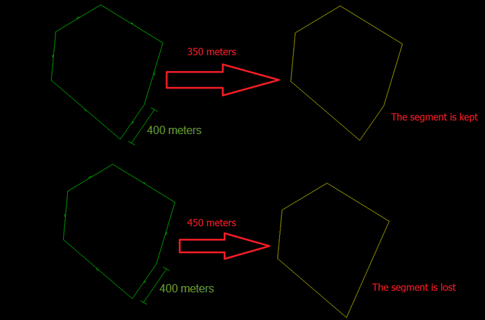
In Diagram 1 below, 400 meters is the distance of the segment, and the values in red (350 and 450 meters) are the values used as the Minimum distance tolerances. In the top example, since the segment is larger than the minimum distance tolerance of 350 meters, it is kept. In the bottom example, however, since the segment is less than the minimum distance tolerance of 450 meters, it is not kept.
1
Minimum angle tolerance
Enter a minimum distance tolerance or use the default setting.
How it works
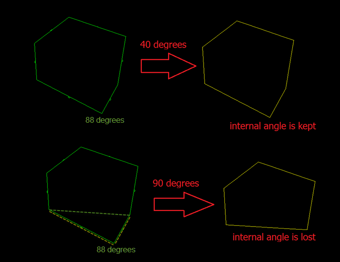
This parameter is used to remove acute, internal angles smaller than the entered value. In Diagram 2 below, 88 degrees is the internal angle in the corner, and the angle in red (40 and 90 degrees) are the values used as the minimum angle tolerance. In the top example, the corner showing an angle of 88 degrees is greater than the minimum angle tolerance, therefore it is kept. However, in the example on the bottom, the corner showing an angle of 88 degrees is less than the minimum angle of tolerance. Therefore, it is removed. Note that the two line segments making up the angle (highlighted by the dashed yellow lines) are removed and a new segment is created that connects the two adjacent vertices.
2
Parallel angle tolerance
E nter a minimum parallel angle tolerance or use the default setting.
How it works
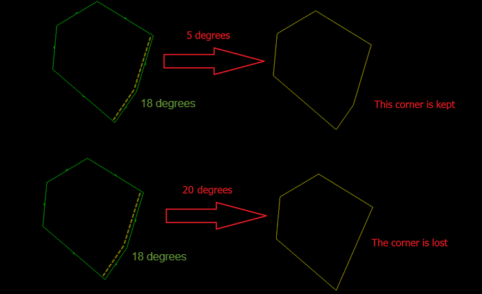
This parameter is used to define if two lines are parallel. If two lines are found to be parallel, they are combined to one. The smallest accepted value is 0 degrees. The default is 5 degrees, and there is no limit to the maximum, but the process will fail if you put an angle close to 90. In Diagram 3 below, the top example shows a line segment (highlighted by a dashed yellow line) with angle of 18 degrees. Since this is greater than the minimum parallel angle tolerance of 5 degrees. Therefore, the angle remains in place. However, in the lower example, the same 18 degree angle is less than the minimum parallel angle tolerance of 20 degrees. Therefore, the angle is removed.
3
Load Defaults
The Load Defaults option to load a previously created default specification file.
Projection Direction
Select the direction for the projection, up or down.
Click Save.
Note: Macros created in versions 7.0 and earlier displays through a text editor. The Notepad application is the default text editor for Windows, however, you can use the ENVIS_EDIT environment variable to reference a different text editor.

