Overview
The Benching and Batters submenu is used primarily in the coal mining sector where there are flat or undulating deposits that can be modelled using 2D surfaces such as grid meshes or triangulations.
Block Layout
The battered block projections can use a 2D block layout as the basis for the projections. For regular coal surfaces, the blocks may have been generated using the Pit Layout option, in which case they are ready to be projected.
For irregular coal surfaces or complex layouts, strings can be digitised onto the surface to represent the walls. Once the string walls are projected, blocks are generated using the Block From Wall option.
Both methods (using blocks and using walls) result in a series of layered polygons defining the blocks which the reserve calculation menu ( Batvol ) uses to calculate the reserves. The two methods are illustrated in the following diagram.
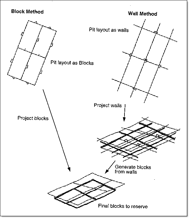
Figure 1 : Block and Wall Method
If blocks come from any other source, (are not created in Vulcan), then the data must conform to the following criteria:
- The mine layout must consist of a set of strips (layers in Vulcan), with each of the strips is made up of a set of blocks (objects)
- The strip (layer) name must be comprised of a strip name and strip number
- The name can be no more than three characters
- The strip number can be no more than three digits
- The number should contain leading zeros, for example '
PN002', 'UPS003'. - The strip (layer) name can be assigned using the Design > Layer Edit > Name option
- The block number (object name) must consist of a three digit number with leading zeros, for example '
003', '111', '999'.- The block number (object name) can be assigned using the Design > Attribute Edit > Name option
- The blocks must be designed in reference to one particular surface, either the lowest seam so they can be projected upward, or the upper or natural surface so they can be projected downward. There is no need to register the blocks to any surface.
- Where the blocks share edges, ensure that the edge points are common. This is done so that when the directions are assigned to the blocks, the option will detect that the edges are shared.
Block Projection
Block projections are handled through a macro file generated using the Create Macro option.
The macro file consists of a series of commands that direct the system how to perform a series of projection operations. The standard commands that may be created by the Create Macro option are shown in the description of the Create Macro option. The maximum number of operational commands in a single macro is 9999.
A standard projection command for example, is to project vertically and upwards. Non standard commands, for example horizontal and downward projections, can also be used, but must be manually added to the file via the Edit Macro option. A list of all available commands is provided in Appendix B.
Geological Model
If the projection is to be done through a series of seam surfaces, then the geological models (grid meshes or triangulations) must be correct. The projections do not take into account the seam masks on grid surfaces, so the models must be continuous and non crossing beyond the mask if it is necessary to project in these regions. If using triangulation models, then the model must extend beyond the range of the projections and berms.
The reserves program ( Batvol ) does use the masks. If a coal block is divided by a seam mask, then the program calculates the coal reserves and classifies the volume outside the mask as smut.

