OB Pattern
Generate Overburden Pattern
The OB Pattern option to create a 2D blast pattern for overburden blasting. This pattern is the basis for creating the blast holes themselves, and the survey peg locations and indicators. This pattern should be correct as to hole location, name, and hole specifications prior to continuing on. A pattern is created in a bay-by-bay basis, with each bay having a given number of rows and echelons.
Instructions
- Select Open Pit menu
- Select Blast Design submenu
- Select OB Pattern option
If the Layout - Setup option has not been selected previously in this Vulcan session, the program will ask for a Bay specification identifier first, as in the Set Up option. Either way, the following panel appears and allows the current bay parameters to be modified. This will not modify the specification file, only the bay parameters current for this Vulcan session. To set the parameters back to those in one of the specification files, select the Set Up option again, as this always reads the specification file.
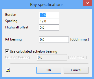
Bay specifications panel
The same situation applies here as for the bay parameters. Select OK to accept the panel.
Upon acceptance, the following panel displays.
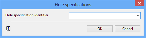
Hole specifications panel
Select the hole specification identifier from the drop-down list. Select OK to accept the panel.
Upon acceptance, the following panel displays.
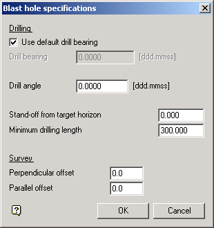
Blast hole specifications panel
This panel and allows the current hole parameters to be edited. These parameters are encoded into each pattern object and can be edited later to reflect special situations. The parameters on this panel should be those needed for the majority of holes in the pattern so that the editing is minimized.
The following panel is then displayed after accepting the Blast hole specifications panel. This panel allows the layout of the pattern to be defined.
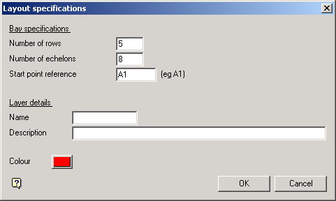
Layout specifications panel
A pattern is created in a bay-by-bay basis, with each bay having a given number of rows and echelons. Enter the number of rows and the number of echelons here. The start point reference gives the starting hole name, and must be a valid hole name. The definition of a valid hole name is given in the Basic Operations section. An invalid name is flagged by the program and must be re-entered.
The layer details define the layer name and description into which the 2D pattern is placed, and the colour defines the colour the pattern will be drawn in. If the layer entered is currently selected, then the pattern will be appended to that layer. If the layer exists in the database, but is not selected, then you will be asked whether you want to select or replace this layer.
The Select layer option will automatically select the layer and then the pattern will be appended to that layer. The Replace this layer option will open a new layer and place the pattern in it. The old layer of this name will be overwritten only if the pattern is saved.
The program does a check in the given layer for the highest echelon number in that layer. If the start point reference has an echelon number less than or equal to this maximum, there may be the possibility of duplicate echelons in this layer. The following message displays.
"Warning - may have duplicate echelon number in this layer"
To continue on and ignore the message, indicate Continue. To go back to the previous panel, indicate Cancel.
The old highwall string is used along with the highwall offset distance to define the position of the last row in the pattern. At the prompt Indicate old highwall string, indicate the string on the screen. The following confirm box will appear and the selected string will be highlighted
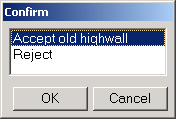
Choosing Accept old highwall will accept that string, whereas Reject will allow another string to be selected.
The 'A' row string is used to define the position of the first row in the pattern. At the Indicate 'A' row string prompt, indicate the 'A' row string on the screen. The following confirm box will appear and the selected string will be highlighted.
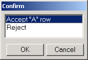
Choosing Accept "A" row will accept that string, whereas Reject will allow another string to be selected.
At the Select start point of pattern prompt, indicate the start point of the pattern. This point need not lay on the 'A' row, as it is projected perpendicular to the pit bearing to intersect the 'A' row string by the program. This means that you can snap onto a block edge and the intersection of the block edge and 'A' row will be taken as the start point (so long as the block edge string and pit bearing are perpendicular). The following confirmation box displays, and the selected point is highlighted
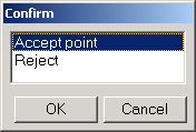
Choosing Accept point will accept that point, whereas Reject will allow another point to be selected.
The bay can proceed in one of two directions that is, basically along the pit bearing or in the reverse of the pit bearing. At the Indicate general direction of bay prompt, indicate a point in the general direction required and a rubber banded line will be drawn away from the indicated start point to help. The program will determine from this point whether the bay is proceeding forwards or backwards in relation to the pit bearing.
The echelon can proceed in one of four directions that is, basically along the pit bearing or in the reverse of the pit bearing, and either 'up' or 'down' from the start point. At the Indicate general direction of echelon prompt, indicate a point in the general direction required and a rubber banded line will be drawn away from the indicated start point to help. The actual echelon direction is based on an angle calculated from the arc tan ( burden / (spacing*0.5) ) which is then applied with respect to the pit bearing. The general direction point is then used to select one out of the four possibilities for the echelon bearing.
The current pattern start point may not be the exact point the pattern is to start from. The following panel appears to enable the start point to be shifted parallel to the bay direction from its indicated point. This option would be more frequently required for the 2nd or subsequent bays when the programÕs calculated start point is not quite correct. The start point shift distance is measured parallel to the bay direction from the current start point, and then projected back onto the 'A' row string to give the new start point.
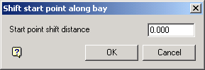
Shift start point along bay panel
The program now has all the required information to calculate the pattern. The following steps are taken when doing this:
- The start point is by definition on the 'A' row string and is the start of the first echelon.
- An arc with radius spacing*number of echelons measured from the start point is intersected with the 'A' row in the general bay direction to give the start of the last echelon.
- A string parallel to the old highwall string but offset at the highwall offset distance (perpendicular to the pit bearing) is formed.
- The first echelon is generated by projecting the start point at the echelon bearing to intersect the offset highwall string.
- The last echelon is calculated in the same way as the first echelon.
- The first row and last row is formed by joining the two ÒAÓ row string intersection points and the two highwall offset string intersection points respectively.
- The default row distances along the first echelon and last echelon are calculated by dividing its length by the number of rows in the pattern.
- Rows are formed by joining their start and end points on the start and end echelons respectively.
The following panel is then displayed to enable changes so as to make the rows not equidistant along the first echelon :
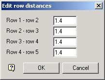
Edit row distances panel
Edit the row separation distances that require change and indicate OK. If any entries have been edited, the program must ensure that the total of all entries is equal to the first echelon length. To do this, the first unedited separation entry after the first edited separation entry will be modified to make all the distances add up to the correct length. If all entries have been modified, then an error will occur if the distances do not match the correct length. Either way, the panel will be re displayed with any program modified entries to ensure it is correct. Indicate OK again to continue on.
The entire pattern is now calculated by rationing out the row separation on the first echelon proportionally on all other echelons. The pattern thus generated is temporarily displayed prior to creating the actual pattern objects. The following confirm box then appears :
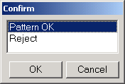
If the pattern is OK, then select Pattern OK, and the pattern will be drawn as actual objects. If the pattern is not OK, then indicate Reject and the row distance panel will appear again to enable changes to be made.
Each pattern hole contains all the hole specification parameters as defined earlier. If the default drill bearing is indicated, the drill bearing will be set to the echelon bearing for overburden holes.
The last echelon of the pattern is not drawn, but its start point is known by the program. This enables a new bay to be generated adjacent to the existing bay, using the existing bay's end points as its default start points. This new bay will have a different bay identifier than the bay just generated. See Basic Operations for more information on bay identifiers.
The following dialog box displays:
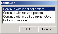
Continue with identical pattern will return you to the Shift Start Point panel. Continue with resized pattern will take you back to the Define Layout specifications panel, but only allow the number of echelons and rows to be altered and will not require the indication of the highwall string, the 'A' row string, the bay and echelon directions or the start point. Continue with modified parameters will take you back to the Bay specifications panel, but as for the previous option many of the steps are not required the 2nd and subsequent times around. The echelon bearing set as default on the Bay Specifications panel will be those used for the currently completed pattern. This enables the next bay to have the same echelon bearing as the current bay.

