Single Hole
Generate Single Holes
The Single Hole option to create single 2D blast pattern holes for overburden or interburden blasting at a given location. This option would most frequently be used to create one off holes for special circumstances. These pattern holes are the basis for creating the blast holes themselves, and the survey peg locations and indicators. Each pattern hole should be correct as to its location, name, and hole specifications prior to continuing on. Holes created with this option are added to the bay with the highest bay identifier in the given layer.
Instructions
- Select Open Pit menu
- Select Blast Design submenu
- Select Single Hole option
If the Layout - Setup option has not been selected previously in this Vulcan session, the program will ask for a Bay specification identifier first, as in the Setup option. Either way, the following panel appears and allows the current bay parameters to be modified. This will not modify the specification file, only the bay parameters current for this Vulcan session. To set the parameters back to those in one of the specification files, select the Setup option again, as this always reads the specification file.
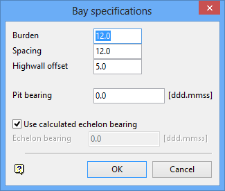
Bay specifications panel
The same situation applies here as for the bay parameters. The following panel appears and allows the current hole parameters to be edited. These parameters are encoded into each hole object and can be edited later to reflect special situations.
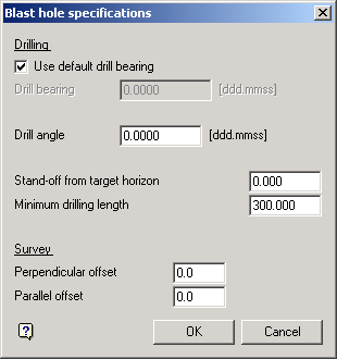
Blast hole specifications panel
The following panel appears, to define the hole to be created :
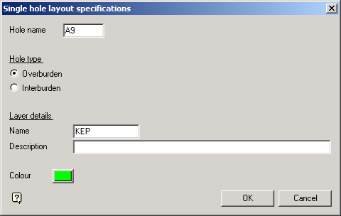
Single hole layout specifications panel
The hole name must be a valid hole name. The definition of a valid hole name is given in the Basic Operations section at the top of this documentation. An invalid name is flagged by the program and must be re-entered.
The hole type, whether overburden or interburden, is required so as to set the drill bearing to either the echelon bearing or the bay direction respectively if the default drill bearing option is used in step 2.
The layer details define the layer name and description into which the hole is placed, and the colour defines the colour the hole will be drawn in. If the layer entered is currently selected, then the hole will be appended to that layer. If the layer exists in the database, but is not selected, then you will be asked whether you want to select the layer or replace it.
The Select layer option will automatically select the layer and then the hole will be appended to that layer. The Replace this layer option will open a new layer and place the hole in it. The old layer of this name will be overwritten only if the pattern is saved.
The program does a check in the given layer for the highest echelon number in that layer. If the hole name has an echelon number less than or equal to this maximum, there may be the possibility of duplicate echelons in this layer. This is flagged by the program with the following panel :
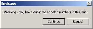
To continue on and ignore the message, indicate Continue. To go back to the previous panel, indicate Cancel.
At the prompt, Select blast hole position, indicate the location of the hole. The following confirm box appears, and the selected point is highlighted
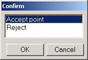
Choosing Accept point will accept that point, whereas Reject will allow another point to be selected.
For interburden holes, the bay direction is required as stated previously to use as the default drill bearing.
The bay can proceed in one of two directions that is, basically along the pit bearing or in the reverse of the pit bearing. At the prompt, Indicate general direction of bay, indicate a point in the general direction required and a rubber banded line will be drawn away from the indicated start point to help. The program will determine from this point whether the bay is proceeding forwards or backwards in relation to the pit bearing.
For overburden holes, the echelon bearing is required as stated previously to use as the default drill bearing.
The echelon can proceed in one of four directions that is, basically along the pit bearing or in the reverse of the pit bearing, and either 'up' or 'down' from the start point. At the prompt, Indicate general direction of echelon, indicate a point in the general direction required and a rubber banded line will be drawn away from the indicated start point to help. The actual echelon direction is based on an angle calculated from the arc tan ( burden / (spacing*0.5) ) which is then applied with respect to the pit bearing. The general direction point is then used to select one out of the four possibilities for the echelon bearing.
The hole is drawn as an object, with the hole parameters stored in it as for the OB and IB Pattern menu options.
The following confirm box appears :
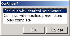
Continue with identical parameters will return you to the Select blast hole position prompt. Continue with modified parameters will take you back to the Bay Specifications panel, but as for the previous option many of the steps are not required the 2nd and subsequent times around. The echelon bearing set as default on the Bay Specifications panel will be those used for the currently completed pattern. This enables the next bay to have the same echelon bearing as the current bay.

