Layout
Create a blasthole pattern
The Layout option to create a general blasthole pattern. To use this option, the polygon that you are going to use as the blast hole layout boundary must be displayed on the screen.
Instructions
- Select Open Pit menu
- Select Blast Hole Layout submenu
- Select Layout option
Select the boundary. This refers to the polygon that defines the boundary of the anchor hole area.
You will then need to select the first and last points in the base line. All 'rows' in the blast hole pattern will be parallel to the base line nominated here. Use
![]() Snap to Objects or
Snap to Objects or
![]() Snap to Points mode to snap onto an existing point. Refer to the Digitise toolbar for details on these modes.
Snap to Points mode to snap onto an existing point. Refer to the Digitise toolbar for details on these modes.
Once the base line has been selected, the Hole Pattern Generation panel displays.
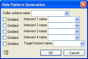
Hole Pattern Generation panel
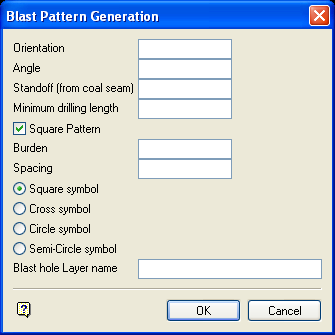
Blast Pattern Generation panel
This panel to set the pattern for the blastholes.
Orientation
Enter the bearing. This value is measured in degrees in decimal format (0.0°-360.0°).
Angle
Enter the dip, measured in degrees (0.0° - 90.0°) from the vertical of the blast hole. Angle of 0° is vertical and an angle of 90° is horizontal.
Standoff (from coal seam)
Enter the vertical distance of the anchor hole above the target horizon. If a target horizon has not been entered in the first panel, then the Standoff will be the absolute depth of the blastholes.
Minimum drilling length
Enter the minimum drilling length. Any hole with a length less than this will not be created.
Square pattern
Select this check box to create a square layout (Diagram 1). If unchecked, then a staggered layout will be assumed (Diagram 2).
Note: The Blast Pattern Generation panel is also displayed when creating single holes (through the Create option). The pattern and row/hole spacing are, however, not applicable and therefore not displayed.
Burden
Enter the distance between adjacent rows in a pattern.
Spacing
Enter the distance between adjacent holes in a row.
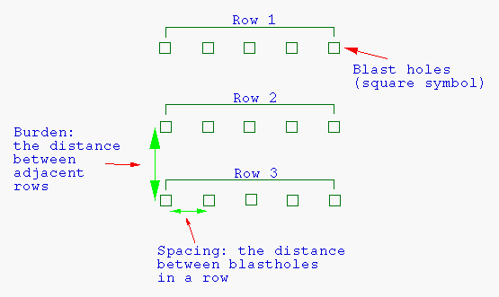
Diagram 1 - Blast Hole Pattern/Square Layout
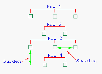
Diagram 2- Blast Hole Pattern/Staggered Layout
The direction of rows is determined by the baseline.
Symbols
Select the symbol to be used for the anchor hole locations. In the above examples, square symbols have been used.
Note: Do not use square symbols if you intend to use the blastholes in surveying.
Blast hole Layer name
Enter the name of the layer for the holes.
To create a new layer, enter the layer name. The layer name:
- may contain up to 40 characters.
- must begin with an alphanumeric character [0-9] or [a-z].
- cannot include spaces.
- can include hyphens [ - ], plus signs [ + ], underscores [ _ ], periods/dots [. ].
- can include the special characters of ÁÂÃÀÇÉÊÍÓÔÕÚÜÑ that are used in the Spanish and Portuguese languages.
Select OK.
Select the alignment of grid. This is a reference point for the positioning of the blast hole pattern (
![]() Snap to point mode can be used to snap onto an existing point). For example, to line the new blast hole pattern up to an adjacent pattern, then a hole in the existing pattern can be used as the reference point. In this way, the new pattern is aligned to the existing blast hole pattern.
Snap to point mode can be used to snap onto an existing point). For example, to line the new blast hole pattern up to an adjacent pattern, then a hole in the existing pattern can be used as the reference point. In this way, the new pattern is aligned to the existing blast hole pattern.
If the reference position falls in the layout area, then a blast hole will be created at that point.
The blast hole pattern is then loaded. Each blast hole exists as an individual object in the nominated layer.

