Generate
Use this option to generate a general hole pattern. You can generate the holes by either using surfaces to define the Z values, or by specifying the Z value explicitly. If you define the Z value explicitly, then you can specify a drill size. The drill size, along with the cost of the hole, will be contained in the report. Use the Report option to generate the report.
Instructions
On the Open Pit menu, point to Hole Design, then click Generate.
Select the boundary polygon (the polygon that defines the hole area).
If you haven't set the default method for designing holes, then the Create Holes panel displays before you are asked to select a boundary polygon.
Select the first and last point in the base line. The base line determines the direction of the pattern. Two points are used to define the base line. Indicate or any of the Snap modes can be used (see the section on Digitising for details on snap modes). All rows in the hole pattern will be parallel to the nominated base line.
Note The base line is commonly parallel to one side of the polygon boundary or points in the polygon boundary can be used.
The panels/prompts that are then displayed depend upon the chosen design method selected. The panels/prompts for both methods are described below.
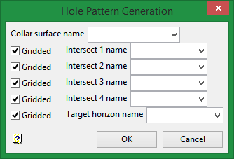
Use surfaces
Input intervals
Use surfaces
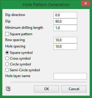
Once the base line has been selected, the Hole Pattern Generation panel displays.
Hole Pattern Generation panel
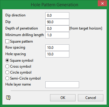
Hole Pattern Generation panel
Dip direction
Enter the dip direction. The dip direction of the holes is a bearing measured in degrees (from North in a clockwise direction) and must be between 0.0° and 360.0°.
Dip
The dip, from horizontal, is also specified in degrees and must be between 0.0° and 90.0°.
Depth of penetration
The depth represents the distance of the hole past the target horizon. If a target horizon has not been specified, then the depth of the penetration will be the absolute depth of the holes.
Minimum drilling length
Enter the minimum drilling length. Any hole with a length less than this will not be created.
Square pattern
Check this check box to create a square layout. If unchecked, then a staggered layout will be assumed.
Row spacing
Enter the distance between adjacent rows in a pattern (shown as Burden in the diagrams below).
Hole spacing
Enter the distance between adjacent holes in a row (shown as Spacing in the diagrams below).
Hole spacing
Enter the distance between adjacent holes in a row (shown as Spacing in the diagrams below).
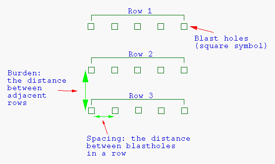
Diagram 1 - Hole Pattern/Square Layout
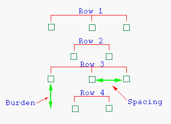
Diagram 2 - Hole Pattern/Staggered Layout
Symbols
Select the symbol to be used for the hole locations. You have a choice of square (used in above diagrams), cross, circle and semicircle.
Hole layer name
Enter the name of the layer in which the holes will be stored. To create a new layer, enter the layer name. The layer name:
-
may contain up to 40 characters.
-
must begin with an alphanumeric character [0-9] or [a-z].
-
cannot include spaces.
-
can include hyphens [ - ], plus signs [ + ], underscores [ _ ], periods/dots [.].
-
can include the special characters of ÁÂÃÀÇÉÊÍÓÔÕÚÜÑ that are used in the Spanish and Portuguese languages.
Select OK.
Select the alignment of the grid. This is a reference point for the position of the hole pattern. For example, to line the new hole pattern up to an adjacent pattern, a hole in the existing pattern can be used as the reference point. In this way, the new pattern is aligned to the existing hole pattern. If the reference position falls in the layout area, then a hole will be created at that point. The reference point can be selected using any of the design entry modes.
A pattern of holes displays in the selected boundary. Each hole exists in the layer as an individual object and is allocated a
?????
(question mark) as the object name. The
Automatic Naming
option can be used to name the holes.
Input intervals
Once the base line has been selected, the Enter collar surface Z value panel displays.
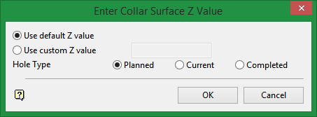
Enter collar surface Z value panel
The following panel is then displayed.
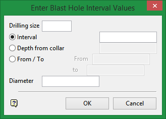
Enter blast hole interval values panel
Drilling size
Enter the drilling size, For example, PQ, HQ, NQ, etc. The drilling size is only for reporting purposes. The report (if you choose to Report Intervals) contains the drilling size, coordinates at the start of the interval, interval length and the cost (the cost is specified in the Report option).
Interval
The interval entered on this panel will be applied to the drilling size. The intervals can be defined in one of three ways:
-
Interval - This to specify the interval as a distance from the previous interval. If there is no previous interval, that is, you are specifying the very first interval, then the distance will be taken from the Z value entered on the Z value panel.
-
Depth from collar - This to specify the interval to an absolute Z value. The previous interval is used as the starting value. If there is no previous interval, that is, you are specifying the very first interval, then the starting value will be the Z value entered on the Z value panel.
-
From / To - This to specify the starting and finishing Z value.
Diameter
Enter the diameter of the hole.
Select OK.
The panel is then redisplayed, allowing you to specify another drilling size and interval.
Note The Diameter field is not shown when the panel is redisplayed.
Select the Cancel option if you have finished specifying intervals. The following panel is then displayed.
Hole Pattern Generation panel
Dip direction
Enter the dip direction. The dip direction of the holes is a bearing measured in degrees (from North in a clockwise direction) and must be between 0.0° and 360.0°.
Dip
The dip, from horizontal, is also specified in degrees and must be between 0.0° and
Minimum drilling length
Enter the minimum drilling length. Any hole with a length less than this will not be created.
Square pattern
Check this check box to create a square layout. If unchecked, then a staggered layout will be assumed.
Row spacing
Enter the distance between adjacent rows in a pattern (shown as Burden in the diagrams below).
Hole spacing
Enter the distance between adjacent holes in a row (shown as Spacing in the diagrams below).
Diagram 3 - Hole Pattern/Square Layout
Diagram 4 - Hole Pattern/Staggered Layout
Symbols
Select the symbol to be used for the hole locations. You have a choice of square (used in above diagrams), cross, circle and semicircle.
Hole layer name
Enter the name of the layer in which the holes will be stored. To create a new layer, enter the layer name. The layer name:
-
may contain up to 40 characters.
-
must begin with an alphanumeric character [0-9] or [a-z].
-
cannot include spaces.
-
can include hyphens [ - ], plus signs [ + ], underscores [ _ ], periods/dots [.].
-
can include the special characters of ÁÂÃÀÇÉÊÍÓÔÕÚÜÑ that are used in the Spanish and Portuguese languages.
Select OK.
Select the alignment of the grid. This is a reference point for the position of the hole pattern. For example, to line the new hole pattern up to an adjacent pattern, a hole in the existing pattern can be used as the reference point. In this way, the new pattern is aligned to the existing hole pattern. If the reference position falls in the layout area, then a hole will be created at that point. The reference point can be selected using any of the design entry modes.
A pattern of holes displays in the selected boundary. Each hole exists in the layer as an individual object and is allocated a
?????
(question mark) as the object name. The
Automatic Naming
option can be used to name the holes.

