Create At Points
Create holes at specific points
The Create At Points option to create blastholes at each point of a selected object. This option also to pass on either the object's name, or the name of its points, to the resulting blastholes.Instructions
- Select Open Pit menu
- Select Hole Design submenu
- Select Create At Points option
The following panel displays.
If you haven't set the default method for designing holes, then the Create Holes panel displays first.
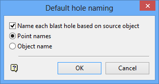
Default hole naming panel
Name each blast hole based on source object
Select this check box to the names of the resulting blastholes to be based on the attributes of the selected object. If this check box checked, then you will need to specify how you want to name the blastholes.
Point names
Select this option to assign the point names to the resulting blastholes.
Object name
Select this option to assign the object's name to the resulting blastholes (the Vulcan standard).
If the Name each blast hole based on source object check box is not checked, then the resulting blastholes will be allocated a ????? (question mark) as the object name. Use the Automatic Naming option to name the holes.
Select OK.
The panels/prompts displayed depend upon the design method chosen through the Set Up option. The panels/prompts for both methods are described below.
Use surfaces
Input intervals
Use surfaces
The following panel displays.
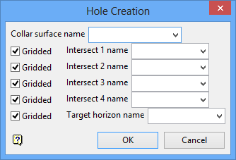
Hole Creation panel
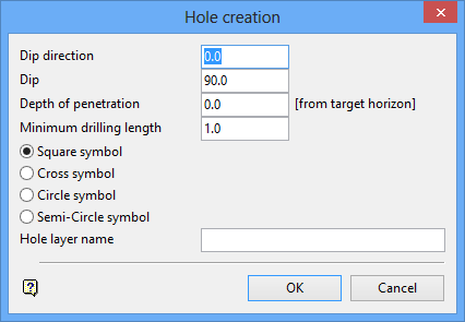
Hole creation panel
Dip direction
Enter the dip direction. The dip direction of the holes is a bearing measured in degrees (from North in a clockwise direction) and must be between 0.0° and 360.0°.
Dip
The dip, from horizontal, is also specified in degrees and must be between 0.0° and 90.0°.
Depth of penetration
The depth represents the distance of the hole past the target horizon. If a target horizon has not been specified, then the depth of the penetration will be the absolute depth of the holes.
Minimum drilling length
Enter the minimum drilling length. Any hole with a length less than this will not be created.
Symbols
Select the symbol to be used for the hole locations. You have a choice of square, cross, circle and semicircle.
Hole layer name
Enter the name of the layer in which the holes will be stored.
To create a new layer, enter the layer name. The layer name:
- may contain up to 40 characters.
- must begin with an alphanumeric character [0-9] or [a-z].
- cannot include spaces.
- can include hyphens [ - ], plus signs [ + ], underscores [ _ ], periods/dots [. ].
- can include the special characters of ÁÂÃÀÇÉÊÍÓÔÕÚÜÑ that are used in the Spanish and Portuguese languages.
Select the OK option to create the blasthole(s).
Input intervals
The following panel displays.
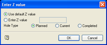
Enter Z value panel
Select the object that will be used to position the holes. Once selected, the following panel displays.
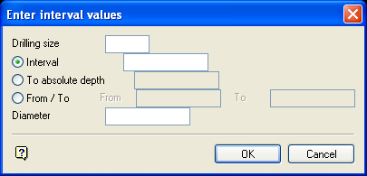
Enter interval values panel
Drilling size
Enter the drilling size, For example, PQ, HQ, NQ, etc.
The drilling size is only for reporting purposes. The report (if you choose to Report Intervals) contains the drilling size, coordinates at the start of the interval, interval length and the cost (the cost is specified in the Report option).
The interval entered on this panel will be applied to the drilling size. The intervals can be defined in one of three ways:
-
Interval
This to specify the interval as a distance from the previous interval. If there is no previous interval, that is, you are specifying the very first interval, then the distance will be taken from the Z value entered on the Z value panel. -
To absolute depth
This to specify the interval to an absolute Z value. The previous interval is used as the starting value. If there is no previous interval, that is, you are specifying the very first interval, then the starting value will be the Z value entered on the Z value panel. -
From/To
This to specify the starting and finishing Z value.
Diameter
Enter the diameter of the hole.
Select OK.
The panel is then redisplayed, allowing you to specify another drilling size and interval.
Note The Diameter field is not shown when the panel is redisplayed.
Select the Cancel option if you have finished specifying intervals. The following panel is then displayed.
Hole creation panel
Dip direction
Enter the dip direction. The dip direction of the holes is a bearing measured in degrees (from North in a clockwise direction) and must be between 0.0° and 360.0°.
Dip
The dip, from horizontal, is also specified in degrees and must be between 0.0° and 90.0°.
Depth of penetration
The depth represents the distance of the hole past the target horizon. If a target horizon has not been specified, then the depth of the penetration will be the absolute depth of the holes.
Minimum drilling length
Enter the minimum drilling length. Any hole with a length less than this will not be created.
Symbols
Select the symbol to be used for the hole locations. You have a choice of square, cross, circle and semicircle.
Hole layer name
Enter the name of the layer in which the holes will be stored.
To create a new layer, enter the layer name. The layer name:
- may contain up to 40 characters.
- must begin with an alphanumeric character [0-9] or [a-z].
- cannot include spaces.
- can include hyphens [ - ], plus signs [ + ], underscores [ _ ], periods/dots [. ].
- can include the special characters of ÁÂÃÀÇÉÊÍÓÔÕÚÜÑ that are used in the Spanish and Portuguese languages.
Select the OK option to create the blasthole(s).

