Split Pit Setup
This option is for creating solid triangulations to send to a scheduler. It is very coal focused. The solids created are attributed with location, geometry and quality data, which is gathered from block models or mining grids.
On the Open Pit menu, point to Integrated Stratigraphic Planning, then click Split Pit Setup.
The panel is mainly divided into six sections:
Specification file
Use the drop-down list to select a specification file (.bss), or click the
![]() icon to browse for one in a different folder.
icon to browse for one in a different folder.
Create a new specification file by typing a new name into the textbox.
If you wish to update an existing file while retaining the old one, select the file you want to modify, then click the Save As
![]() icon.
icon.
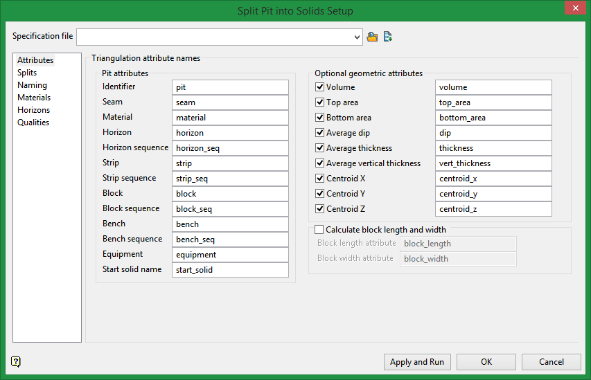
Attributes
Triangulation attribute names
This controls the names of the triangulation attributes used by the splitting process.
The left hand side of the panel are the splitter attributes assigned as the options runs. You can select the attribute names you want to use or use the default set of names.
Identifier
An attribute based on the pit solid so that it is known that a given solid came originally from a given pit.
Seam
The name of the seam associated with the solid.
Material
The type of material associated with the solid. For example it could be ‘coal’ or ‘waste’ or ‘midburden’ etc.
Horizon
The name of the horizon associated with the solid. This is normally based on the seam name and if it is burden or product, for example eg seama_co and seama_bd for seam A coal and seam A burden.
Horizon sequence
The integer sequence number of the horizon in the horizon list from the bottom up, plus an optional offset.
Strip
The name of the mining strip that is associated with the solid. Strips are named as defined in the Strip tab.
Strip sequence
The integer sequence number of the strip in the strip advance direction, plus an optional offset.
Block
The name of the mining block associated with the solid. How blocks are named is defined by the user in the Block tab.
Block sequence
The integer sequence number of the block in the block advance direction, plus an optional offset.
Bench
The name of the bench which is usually the level of the bench. How benches are named is defined by the user in the Bench tab.
Bench sequence
The integer sequence number of the bench from the bottom up, plus an optional offset.
Equipment
The name of the attribute to use for the mining equipment. This is only supported by allowing the user to set the equipment name per material type, as defined on the Equipment tab.
Optional geometric attributes
The right hand side of the panel are the names of the geometric attributes that can be optionally calculated and set as attributes in the triangulation. If you don’t need the calculation you can unselect it.
Volume
The solid volume
Top area
The area of the top of the solid, based on the sum of the surface area of triangles with normals pointing upwards.
Bottom area
Similar to top area but for triangles that have normal pointing downwards.
Average dip
The area weighted average of the dip of the top and bottom surface triangles.
Average thickness
The volume divided by the larger of the top or bottom area.
Average vertical thickness
Will sample the vertical thickness of the solid using a grid pattern, and calculate an average of the samples.
Centroid values
These are calculated as the volume weighted centroid X, Y, and Z location.
Splits
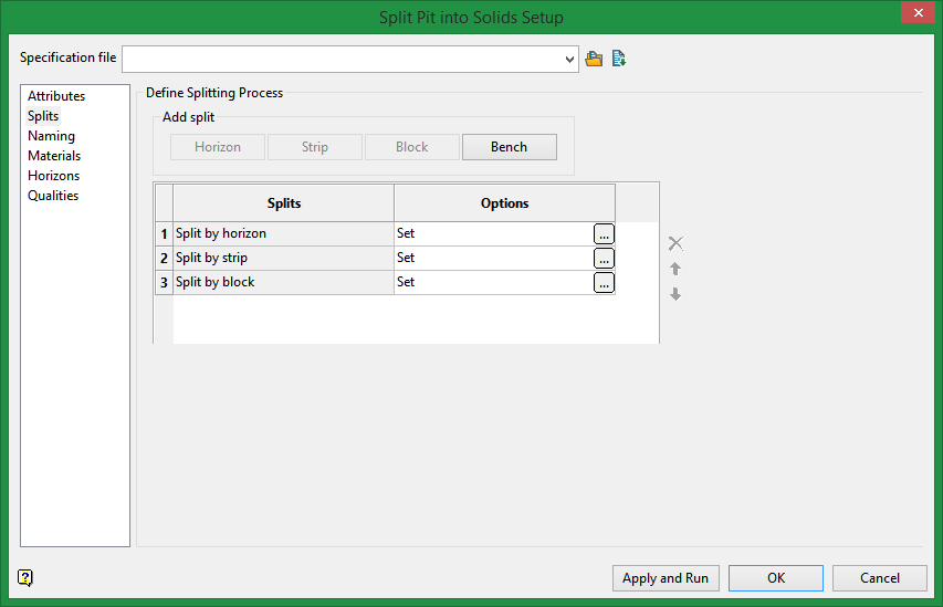
Define Splitting Process
Note: To reduce processing time, it is recommended to split by horizon first.
Compared to splitting by strip, block, or bench, splitting a solid by horizons can be a time consuming process. By reducing the number of solids that must be split by horizon to a minimum, the overall running time is drastically reduced. This can be done by keeping this step at the start of the process before any other splits are done. If you need to split multiple input solids by horizon (for example if you already have the pit cut into strips and blocks), it may be more efficient to start from the beginning by splitting the original pit solid by horizon, then use other splitting methods.
Add Split
Horizon
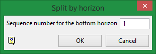
Enter the starting sequence number for the bottom horizon, the click OK.
Strip
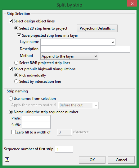
Strip selection
This option chops all the horizon solids up using the strip highwalls. This gives the strip solids. These are attributed with the seam name, and the strip name.
Note Usually the strip lines and blocks lines will be basically perpendicular to each other. Whereas strip lines can be internally projected up through the horizons using a benching and battering approach, a block line will only be internally projected vertically to create the face for cutting the solids. A prebuilt triangulation will not be modified at all. It is just used to cut the solid. As with strips you can mix prebuilt cutting surfaces with lines. However, make sure the faces do not cross otherwise the Booleaned results will not be good.
Select design object lines
These are polyline objects you have loaded or created.
Select prebuilt highwall triangulations
If using pre-built highwall surfaces, you should ensure that your surfaces are of sufficient extent in all axes to enable splitting to proceed successfully.
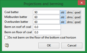
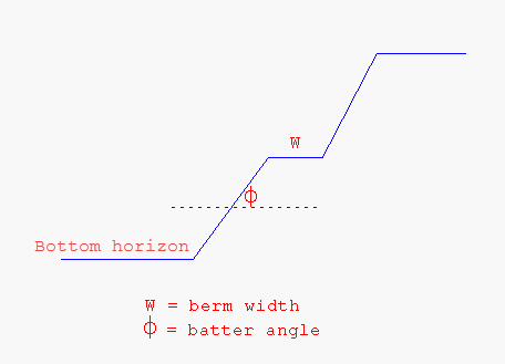
Projections and berming
Enter the batter angle and berm width. These are the default angles and berming distances that are used when the splitter is internally creating high walls for use with splitting by strip. It is the same idea as the Benching and Batters defaults panel. Optionally the user can turn off berming along the bottom surface floor, but berm on all others.
Do not berm on the bottom horizon floor of coal
Select this option if you do not want the width you established in Berm on floor of coal to include the bottom horizon.
Strip naming
Strip naming can be based on the selection where it will use object names and/or highwall triangulation names, or you can name using the strip direction sequence number, a zero fill width (such as 001, 002, etc), and a prefix and suffix. Strip names must be unique.
At the time of selection, indicate a direction of strip advance and this will be used for the selection and strip sequence counter.
Block
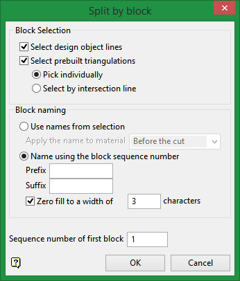
Block selection
This options chops the strip solids by the block faces, giving you the block solids. These are attributed with the seam name, the strip name, and the block name.
Note Split Pit does not support polygons for cutting, only lines and surfaces. Where it says block it means block lines or surfaces and nothing to do with block modelling.
Select design object lines
These are polyline objects you have loaded or created.
Select prebuilt highwall triangulations
These are surfaces describing the block face and should extend above and below the pit solid being cut. If they do not, you will get Boolean issues. You can select prebuilt surfaces one by one from the screen. You can also select them by intersection with the block advance direction line, which you will need to digitise.
Block naming
Naming for blocks can come from the names of the design objects and prebuilt triangulations (ex., B1.00t will give the block the name ‘B1’, whereas an object called ‘BLOCK1’ will give the block the name ‘BLOCK1’).
Otherwise the block sequence number can be used to name the blocks, where the first selected block is numbered based on the Sequence number for the first selected block entry. For example, if you digitise from right to left, and have 10 as your starting sequence number, then the block created to the left of the first block line or face will be named 10, the next one 11, etc.
Prefix / Suffix / Zero fill
You can also add a prefix and suffix, and zero fill to the naming convention. As an example, suppose you had blocks that were named 10, 11 and 12. With a Prefix set as B, a Suffix set as A, and Zero fill set to 4 characters, the results would be B0010A, B0011A, B0012A, etc.
Note The Zero fill parameter does not include the spaces set aside for the prefix or suffix.
Bench
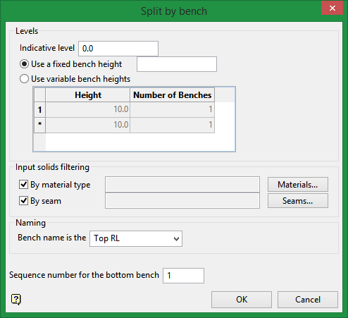
Levels
Indicative level
Indicative level is a Z-value where a bench would pass through. So if you have an indicative level of 5.123, and a single bench height of 10, then a bench could pass through the infinite number of matching levels which include -5.123, 5.123, 15.123, 25.123 etc. So if your pit ranges from RL 10 to RL 30, then the option will be trying to bench block solids at 15.123 and 25.123, as these are the only two levels that match the indicative level and bench height that pass through the Z extent of the pit.
Use variable bench heights
For the variable bench heights a pattern of bench heights can be defined. The bottom of the pattern will always pass through the indicative RL, and the pattern will be infinitely continued above and below the indicative RL. For example, if the pattern is 3, 4, 4, and the indicative level is 10, then the benches can pass through 10, 13, 17, 21, 24, 28, 32 etc repeating forever. It will also pass through -1, 2, 6 etc. Because the pattern is 11 units, it restarts at every 11 units above and below the indicative RL. So if the pit has an RL range of 5 to 15, benches will occur at 6, 10, and 13.
Input solids filtering
With benching, there may be times when you only want to bench the overburden or specific seams. So we have added filtering by material type and by seam name where you can select from the list of seams supplied on the Horizons tab. Within each category OR is used (for example, Seam A or Seam B), but if you specify both categories, both need to be true. Only those solids with attributes that match both the material type(s) and seam(s) selected will benched. For example, if you want only the overburden to be benched, select material type overburden if that is what you used. Similarly, you may need to select material type waste and seam name OB to get the desired result.
Naming
In the naming format you will see it always has [bench] which is the bench name and is substituted with the bench level of the cut at the time of cutting. This bench level used can be based on the top of the bench or the bottom of the bench – this is what drop-down list entitled bench name is the is for.
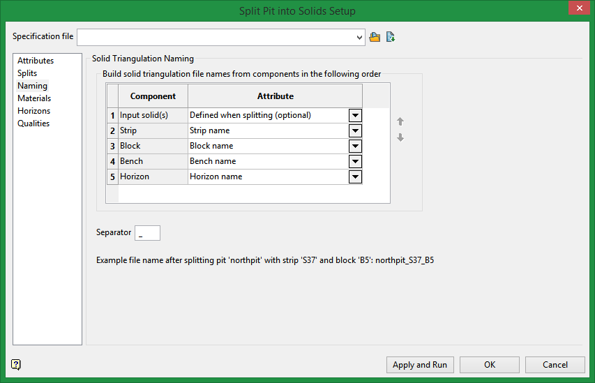
Solid Triangulation Naming
Highlight a row, then use the up and down arrows to arrange the order of the naming components.
Attributes consist of either the name or sequence of each component.
Materials
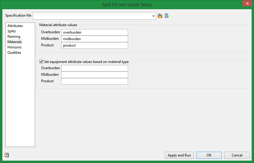
Material attribute values
Overburden / Midburden
Enter the material attribute values here.
Product
For product value, you may decide to enter something more descriptive than product such as coal.
Set equipment attribute values based on material type
Select this option if the attributes for the equipment that is used are based on the material type you are working with.
Horizons
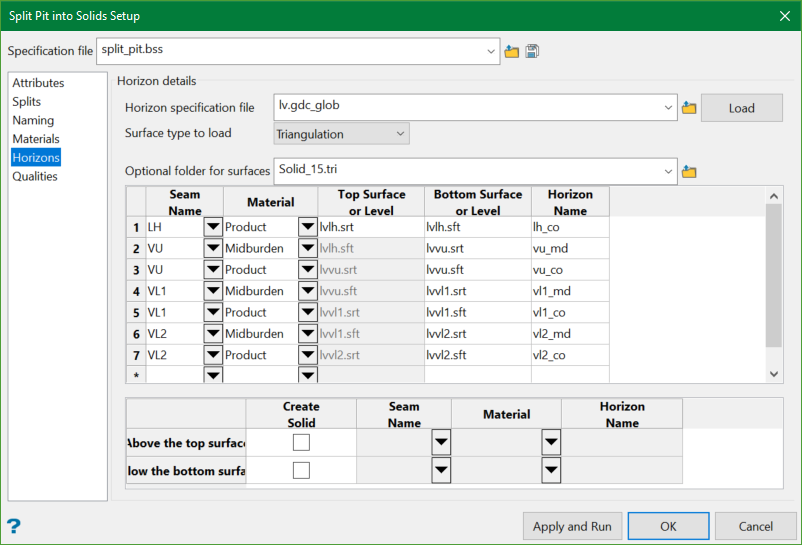
Horizon details
You can define the horizons that you want to consider when splitting by horizon. You can optionally load previously created horizon information from a Glob file, a Benching and Batters specification file, or a Horizon List file. The horizon column is formed automatically when loading one of the horizon specification files by appending _md for midburden, and _co for product. The entries in the horizon column must be unique.
Optionally, you can process only material between the horizons, or process the part of the pit above and/or below the top and bottom horizon surfaces respectively. However, you can enter the top and bottom bench levels directly in the horizon grid and the bench surfaces will automatically be created during the splitting run.
When used, the horizons will be stacked from top down to ensure that they don’t cross or touch. This enables a clean split to be made per horizon. Grids are more efficient for this stacking step. If mixing grids and triangulation horizon surfaces, your triangulations must be above any grids in the stratigraphic sequence.
If you are modelling parent and child seams, ensure that the grids are pinched and not masked. If you are modelling the parent as plies, you will need child grids modelled to the full extent of the mine area.
If in Bench mode, you will need to define the name of the solids created. In Horizon mode this option is not available. The naming style used is consistent across the option and is a format which can contain the attribute names defined on the Attributes tab which must be placed within square brackets, plus optional other text and numbers. For example, the default name for a solid split by horizon when using Bench mode is [bench]_[strip]_[block]_[horizon].00t, where the bench name, strip name, block name and horizon name for that solid will be substituted in. So you may get something like 510_s004_001_a_md.00t, which is the name of a solid from bench 510, strip s004, block 001, and horizon seam A midburden. The solid names will need to be unique for a given splitting step (as all solids for that step go into one folder), and because in this particular case this step will be done after the splitting by bench, strip, and block, all these parts will need to be in the name to make it unique. This is validated by the option.
Note: If you choose .gdc_glob file in the horizon specification file, the Surface type to load drop-down list is enabled from where you can choose to select either triangulation or grid. If you choose triangulation, the panel will populate all .srt and .sft triangulation surfaces instead of traditional grids.
Qualities
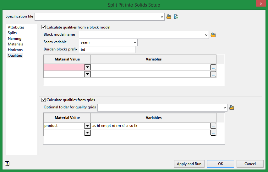
The starting point is that are a group of solid triangulations which have attributes assigned from the splitting run, so it knows which are waste solids or what seams they are for already. They need some quality attributes set AS TRIANGULATION ATTRIBUTES on the solids. This does not set qualities into the block model. The HARP model already has them all in it. This entire menu option is for creating attributed solids to be exported to a scheduler.
Calculate qualities from grids
Quality grids are already defined by naming convention for one seam and are for product normally, but a block model has all the seams and waste and product in it, so extra information needs to be supplied so the correct qualities can be read.
On this panel you define qualities based on material value. This is because normally we only want to get qualities for product, not for waste. Therefore, the panel lets you select the material value and the qualities you want read for that material value. For example, you might call your coal material product, and both interburden and overburden waste, and define qualities on the panel only for product. We know the solids being processed will already have their material triangulation attribute set to either product or waste once the cutting has finished. Therefore,when the qualities are read with this specification, it will only process the triangulations with a material value that matches product.
Optional folder for quality grids
Use the drop-down list to choose a folder in which to store the generated solids. You may also type the name of a new folder and one will be generated.
Variables
Method
Centroid
Drop the centroid of the solid XY value onto the quality grid and read a single value. This is also a fallback if the other methods fail to get a valid value.
Average
For each quality grid model vertex that sits in the XY of the solid, get a value and average the results.
Thickness weighted
This is the same as average, except the vertical thickness of the solid at the XY locations is used to weight the quality value read from the grid.
Calculate qualities from a block model
Normally you would be using a HARP model here which has an indication of what blocks are for what seam, and what blocks are waste (HARP models have a seam variable (normally seam) and use a prefix naming convention for waste blocks, normally bd, and is full of quality data stored in hundreds of variables in the blocks. Therefore, other block models will not be that useful.
Variable
Method
Centroid
Drop the centroid solid XY value vertically through the block model and sample the block values that match the seam and material type. If more than one block is matched, the quality will be block volume weighted. This can happen when the Harp model has plies in it. This is also a fallback if the other methods fail to get a valid value.
Average
This uses the block size from the first or second block scheme as a sampling cell size and samples at the block centroid XY values that overlap the solid being processed, then averages the samples.
Thickness weighed
This is the same as average except the vertical thickness of the solid at the XY locations is used to weight the quality value read from the block model.

