Data Mapping
Map Monitor Data to Database Fields
The Data Mapping option to map the monitor fields, required by the Monitoring module, to the monitoring database fields without the need to set up synonyms in the datasheet. The Data Mapping option also to specify the format of the fields, For example, length and number of decimal places, as well as the units of measurement to be used for any output, and the fields to be exported.
The mapping information is stored in the
<proj>.mon_spec
file.
Note Do not select the Data Mapping option when monitor data is already loaded onscreen. To change the onscreen data, use the Display Settings option. To change the data mapping, first clear the currently loaded data.
Instructions
On the Open Pit menu, point to Monitoring, and then click Data Mapping to display the Data mapping name panel.
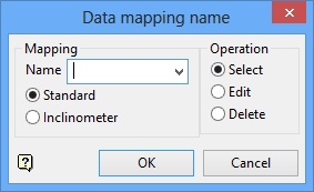
Mapping
Name
Different sets of mapping parameters may be specified. Each set is identified by a user-defined mapping name and stored in the
<proj>.mon_spec
specification file. See Appendix A for an example. Existing mapping names can be entered manually or selected from the drop-down list. The maximum size of the mapping name is 10 alphanumeric characters (spaces are not allowed).
Standard
Select this option to use a standard monitor. A standard monitor can either be a prism or a wire extensometer. A prism, is a moving monitor that has XYZ positions for each time interval. Prisms are used for recording bench or wall movements in open cut mines, or slope movements in engineering and geotechnical studies.
A wire extensometer, is a stationary monitor that has XYZ positions that do not change for each time interval. Wire extensometers are used for recording strain and elongation measurements.
Inclinometer
Select this option to use a inclinometer monitor. An inclinometer is a special type of monitor used to record change in borehole deviation over time, and is used in slope stability monitoring. Inclinometers differ from the standard monitor because they have multiple positions per time sample that are stored in the database with one key per sampling time (like a group of prisms).
Operation
Select
Select this option to load an existing set of mapping parameters.
Edit
Select this option to create a new set of mapping parameters or load an existing set for editing purposes. You must do this before loading any data onto the screen.
Delete
Select this option to delete an existing set of mapping parameters.
Click OK.
A database mapping panel is then displayed. The type of database mapping panel displayed is dependant upon the selected monitor type, that is, standard or inclinometer.
- Standard monitor
- Inclinometer monitor
Standard monitor
The header record contains the monitor name and, if the monitor is stationary, its position. The sample record contains a date and/or time field and, if the monitor is moving, its starting position. Any number of user definable fields may exist in both the header and sample record. We recommend that you set a number of extra fields for later use, such as FilterX, FilterY, FilterZ, Filterslope, etc.
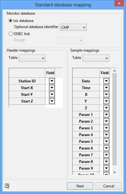
Monitor database
Isis File
Select this option to nominate an Isis database. The available drop-down list displays all Isis database files found in your current working directory. Click Browse to select a file from another location.
ODBC Link
Select this option to nominate an ODBC link database. Select the design name from the drop-down list.
Once these features are specified, you can map the monitor fields to the fields required by the Monitoring module. The monitor fields can be entered manually or selected from the available drop-down lists.
The Start X/Y/Z fields in the Header mappings are used for stationary monitors. The X/Y/Z fields in the Sample mappings are used for moving monitors. You cannot have both X/Y/Z fields filled out in both the Header and Sample records.
Up to 10 fields can be mapped, For example, slope distance. These fields are referred to in this module as the "extra parameters".
All entries in the Standard database mapping panel are stored in the
<proj>.<monitorname>_spec
file as follows:
BEGIN$TAB <mappingname>_MAP ' ' ' ' ' ' END$TAB <mappingname>_MAP
Inclinometer monitor
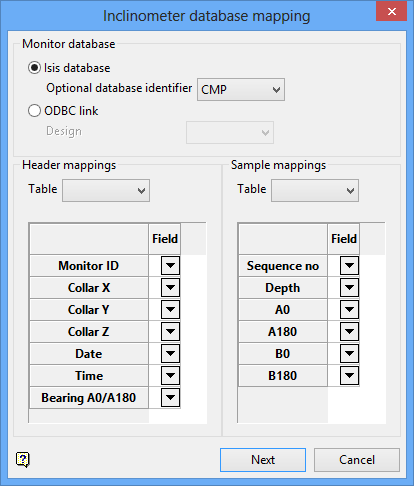
The Inclinometer database mapping panel is similar to the Standard database mapping panel. The main difference is that the header record contains the monitor name, collar location, sample time and bore direction. The sample record contains sample sequence, depth and tilt on casing axes.
All entries in the Inclinometer database mapping panel are stored in the
<proj>.<monitorname>_spec
file as follows:
BEGIN$TAB <mappingname>_MAP_H ' ' ' ' ' ' END$TAB <mappingname>_MAP_H
Click Next.
The following panel is then displayed.
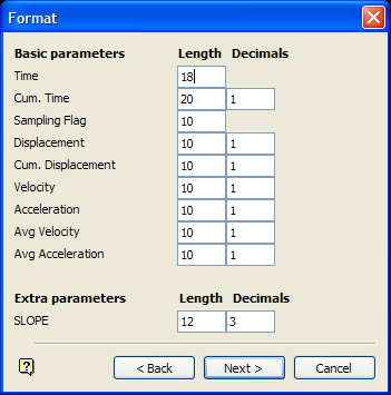
The Format panel to specify the length and the number of decimal places of the fields for display and reporting purposes. The length of the field should be at least as long as the data fields in the database, otherwise data may be cut off. The Format panel for inclinometers is similar to the panel for the standard monitors.
Basic parameters
The Basic parameters section refers to the position of the monitor. These parameters are Time, Cumulative time (relative to start), Sampling Flag (used to indicate a real or interpolated sample), Displacement, Cumulative Displacement (relative to starting position), Velocity, Acceleration, Average velocity and Average acceleration. These field values are calculated from the monitor locations at each time interval.
Extra parameters
The Extra parameters section refers to user definable fields, such as slope distance. These fields are defined in the previous database mapping panel, and are only displayed if these fields exist.
All entries in the Format panel are stored in the
<proj>.<monitorname>_spec
specification file as:

