Berm string
Use the Berm string option to project a berm or bench from a nominated pit or dump outline.
If berms of varying widths are required, then you will need to assign berm values to each face (using the Assign Berm/Batter values option) before using this option. Also note that the direction of digitising determines the sense of the projection. Clockwise strings project outwards, and anticlockwise strings project inwards. If the direction of digitising is unknown, then use the Analyse > Label > Point Label option.
Instructions
Click the Berm string button
![]() from the Open Cut Design toolbar.
from the Open Cut Design toolbar.
or
On the Open Pit menu, point to Open Cut Design, and then click Berm String.
Select the pit/dump outline to berm. Once selected, the following panel displays.
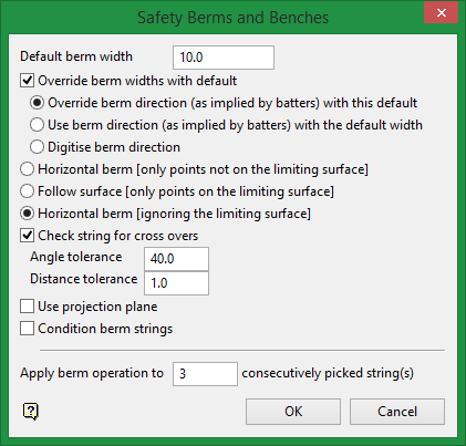
Default berm width
Enter a default berm width value. Any faces that have not been assigned berm widths will be assigned this default value. The berm width is held in the W-tag of the points of the line segment(s), making up the pit string. The value applies to the segment following the point in the digitising sequence. Unassigned faces will have point W-tags = 0. The unit of measurement is set in the
.dg1
file. The default berm width can also be used to replace all existing berm widths.
Override berm widths with default
Select this check box to replace all existing berm widths with the default width. For example, when entering 10.0, all faces will be projected out 10 metres (33 feet), regardless of berm widths that may have been assigned previously to the outline.
If unchecked, then any berm widths that have previously been assigned will be used in the projection. The default berm width will only be used when a berm width has not been assigned to a face.
Berm widths used in the projection are retained in the projected string so that it can be used for the next projection.
Override berm direction (as implied by batters) with this default
Select this check box to change the existing berm direction to the sign of the default berm width. For pit strings, use positive for outward berms and negative for inward berms. For dump strings, use negative for outward berms and positive for inward berms.
You can choose from one of three methods to project the berm. The first two methods refer to situations where the nominated outline has been projected onto a triangulation or grid mesh surface (For example, using the Project string option in the same submenu), the third method refers to outlines that have not been projected onto a triangulated or gridded surface.
Horizontal berm [only points not on the limiting surface]
Select this option to create a horizontal berm around the part of the outline that did not intersect with the nominated triangulation or grid mesh surface when it was projected. Where the string has intersected the surface, the berm will not be projected. See the following diagram.
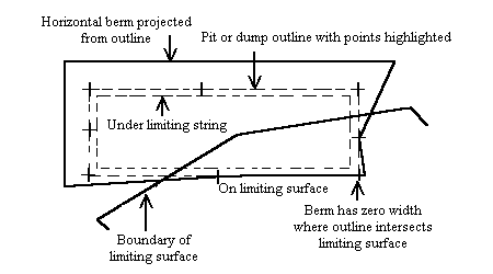
Diagram 1 - Creating a Horizontal Berm
Follow surface [Only points on the limiting surface]
Select this option to follow the surface when projecting the berm. All points of the projected berm that lie (in Plan View) on the triangulation or grid mesh surface will be registered onto that surface. Points that lie outside the surface area are projected horizontally.
Horizontal berm [Ignoring the limiting surface]
Select this option to project a horizontal berm, regardless of whether or not the outline had been projected onto a triangulation or grid mesh surface, that is, a horizontal berm is projected around the entire outline.
Check string for cross cross-overs
Berming will cause an object to 'shrink' or 'grow'. As a result crossovers may occur, that is,, 'butterflies' can form at some corners. Select this check box to remove these crossovers (refer to the Tolerance option).
Use projection plane
Select this check box to berm in sections by defining a projection plane. If checked, then upon completion of the current panel, the Projection Plane definition panel displays.
Condition berm strings
Select this check box to check the nominated toe or crest strings to determine whether points need to be added or deleted to satisfy specified conditions.
Apply berm operation to [ ### ] consecutively picked string(s)
Enter the number of berm string you want to create. A new string will be created with the width offset that was entered in Default berm width.
Click OK.
If you chose to condition the berm strings, then the String Conditioning panel displays.
Use angle tolerance check
Select this check box if you want to use an angle tolerance to check the nominated toe/crest strings. You will need to enter the minimum and maximum angles.
Use distance tolerance check
Check this box if you want to use a distance tolerance to check the nominated toe/crest strings. You will need to enter the minimum and maximum segment lengths.
Use curves on corners
Check this box if you want to replace the sharp angles in the pit outline with curves.
Radius of curvature
Select this option to specify the radius of curvature. This means that the curve will be formed so that the distance of the tangent points from the apex of he line segments is variable to accommodate a curve of fixed (nominated) radius of curvature. Changing the angle between the line segments will change the distance from the apex to the tangent points.
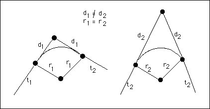
Diagram 1 - Fixed Radius
Tangent offset from point to intersection
Select this option to specify the curve by a tangent offset from the point of intersection. This means that the distance "d" is constant, and the radius of curvature is varied to accommodate different angles of the line segments.
The number of points used to represent the curve also needs to be specified. The minimum number of points is 3.
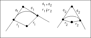
Diagram 2 - Tangent offset from Intersection Point
Generate curve in plane of line segments
Select this check box if you want to generate the curve in the plane of the line segments. You will need to enter the angle tolerance at which corners are to be replaced by curves. Angles that are greater than this tolerance will not be affected, while angles that are less than this tolerance will be replaced by curves. If this check box is not selected, then the curve applied will be in Plan View.
Angle tolerance
Enter the angle tolerance at which corners are to be replaced by curves. Angles that are greater than this tolerance will not be affected, while angles that are less than this tolerance will be replaced by curves.
Apply curve to points on a zero width berm
Select this check box to apply curves to points on a zero width berm. This check box is not usually selected as points, which are the points of intersection between the ramp and the pit outline, should not have curves applied. They should remain as approximate 90° angles. These points have a W tag value of 0 (zero) and can therefore be excluded from the application of curves. If this check box is selected, then curves will be applied to these points.
Restrict by polygon
Select this check box to condition strings contained inside or outside of a polygon. Select either the Inside or the Outside option to smooth the strings contained inside or outside of the chosen polygon. If this box is selected, you will be prompted to select a limiting polygon on completion of this panel.
The W value can be obtained from either the left point, the right point or the weighted average. The weighted average should, however, be used with care (refer to the note at the start of this option's description).
Click OK.
The projected outline is then displayed as a highlighted string. You will then be asked whether or not you want to keep the projection. Upon confirmation, you can select another pit/dump outline to berm. Cancel when finished selecting pit/dump outlines.
If berming in sections, then the Projection Plane panel displays before you are asked to confirm the projection.
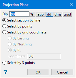
Projection Plane panel
Dip
The dip is the angle of the section from horizontal. Valid dip angles are between -90° and 90°.
Select section by line
Select this option to define the plane by selecting an existing line and specifying the dip.
Only design strings may be picked and it is not possible to pick a line in an underlay. The direction of the view, and therefore the direction of the stepping, depends on the digitised sequence of the line. The digitised sequence of the line can be reversed using the Design > Object Edit > Reverse option.
Select by points
Select this option to define the plane by digitising two points and specifying the dip.
To locate a point precisely, use the Snap to Objects or Snap to Points modes (on the Digitise toolbar). Points may be snapped onto underlays, such as block model slices or triangulations. If you use Indicate mode to select the points, then the points have the current default Z value.
Select by grid coordinate
Select this option to define the plane by using a specific grid coordinate. The grid co-ordinates can contain up to three decimal places. To achieve the best results for the following three methods, we recommend using the Zoom Data Extents icon (on the Graphics toolbar) in order to view all of the graphics.
- By Easting - Select this option to enter a specific Easting value (X value).
- By Northing - Select this option to enter a specific Northing value (Y value).
- By RL - Select this option to enter a specific RL value (Z value).
Select by 3 points
Select this option to define the plane by digitising 3 points. To locate a point precisely, use the Snap to Objects or Snap to Points modes (on the Digitise toolbar). Points may be snapped onto underlays, such as block model slices or triangulations.
Using this option will allow you to explicitly define the location and orientation of a plane by indicating 3 points. The first two points define the bearing of the plane, and the third point defines the dip of the plane.
Click OK.

