Auto Pit
Use this option to generate a pit or dump from a selected outline, using constant bench heights and widths. The pit/dump can be limited to a nominated depth or limited by approximate volume. You can also interactively generate double or triple benches and change the projection parameters, such as batter angle, berm width and bench height.
The direction of digitising determines the sense of projection:
-
Use a clockwise string for a pit because it will be projected upward and outward, or downward and inward.
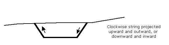
Diagram 1 - Clockwise String
-
Use an anticlockwise string for dumps because it will be projected upward and inward or downward and outward.
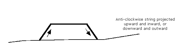
Diagram 2 - Anticlockwise String
If the direction of digitising is unknown, then use the Analyse > Label > Point Label option. The Design > Object Edit > Reverse and Design > Object Edit > Advanced Reverse options can be used to reverse the sequence of digitising.
To use this option an outline, defined as a toe or a crest through the Flag Toe/Crest string option, must be displayed.
Instructions
Click the Auto Pit button
![]() from the Open Cut Design toolbar.
from the Open Cut Design toolbar.
or
On the Open Pit menu, point to Open Cut Design, and then click Auto Pit.
Select the pit outline. The following panel is then displayed.
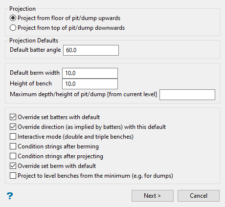
The projection may either be from the floor of the outline upwards or from the top of the outline downwards.
Project from floor
Select this option to project the outline upwards. Use a clockwise string for a pit projection and an anticlockwise string for a dump projection.
Project from top
Select this option to project the outline downwards. Use a clockwise string for pit projection and an anticlockwise string for a dump projection.
Default batter angle
Enter the default batter angle. This angle will be applied to faces that have not been assigned (by using the Assign Berm/Batter values option) a batter angle. It is possible to alter this value while generating the pit if you select the Interactive mode (double and triple benches) option on this panel.
Override set batters with default
Select this check box to replace all existing batter angles with the above angle, that is,, including angles that were previously assigned.
For example: If you specify a default batter angle of 60°, all faces are projected at 60°, regardless of batter angles that have been assigned to the outline. If this check box is not checked, then any assigned batter angle is used in the projection. The default value will only be used when a face has not been assigned a batter angle.
Batter angles used in the projection are retained in each projected batter face and will be used in subsequent batter projections.
Default berm width
Enter the default berm width. This default value will be used for all faces that have not been assigned (by using the Assign Berm/Batter values option) a berm width. This means faces with a berm width of 0.0. The default berm width can also be used to replace all existing berm widths. See the Override berm widths with default option below. It is possible to alter this default value while generating the pit if you select the Interactive mode (double and triple benches) option on this panel.
Override berm widths with default
Select this check box to replace all existing berm widths with the above specified width.
For example: When entering 10.0 all faces are projected 10 metres (33 feet), regardless of berm widths that have been assigned to the outline. If this check box is not checked, then any assigned berm widths are used in the projection. The default berm width will only be used when a berm width has not been assigned to a face.
Berm widths used in the projection are also retained so that they can be used in subsequent berm projections.
Height of bench
Enter the bench height, which is the vertical distance that each outline is projected. It is possible to alter this default value while generating the pit if you select the Interactive mode (double and triple benches) option on this panel.
Project to level benches from the minimum
Select this check box to create horizontal benches from variable Z outlines. Similar to using the "m" outline in the Project string option. If unchecked, then each projected bench will retain the relative Z values of the nominated outline, similar to using the "r" outline in the Project string option.
Maximum depth/height of pit/dump
Enter the maximum depth/height for the projection. This allows you to limit the projection to a maximum depth/height relative to the Z value of the outline.
For example: If the outline is at Z = 1000 and we want to project the pit up to Z = 1300, the maximum depth/height should be 300.0 metres.
Interactive mode (double bench and triple bench)
Select this option to generate the pit interactively. Choose whether to generate single, double or triple benches (or all three in one pit) and to alter the default batter angle, berm width and bench height.
Condition strings after berming
Select this check box to condition the strings after berming. For more information refer to the Condition string option.
Condition strings after projecting
Select this check box to condition the strings after projecting. For more information refer to the Condition string option
Two other projection limiting options are available on the next panel. These two methods refer to limiting the projection by volume or to a surface model. You can select one or more of these limiting options to achieve the desired effect. If no limitation is set at all, then the projection will continue to be generated until there is no more space available.
Click OK.
The following panel with the next two limiting options displays.
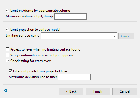
Limit pit/dump by approximate volume
Select this check box to limit by volume. Specify the maximum volume of the pit/dump. Generation continues until the resulting pit/dump first exceeds the nominated volume. Volumes are approximated by multiplying the plan area of each bench by the bench height.
Limit projection to surface model
Select this check box to limit the projection to an existing (not necessarily loaded) triangulation or grid. Specify the limiting surface name.
Project to level when no limiting surface found
Select this check box when projecting to a grid or triangulation surface and if part of the projection does not intersect with that surface. If this check box is left unchecked, then the part of the bench that does not intersect will retain the same Z values as the original outline.
Note You must specify a grid or triangulation surface for outlines with zero batter angles, that is, the default batter angle is set to '0.0'.
Verify continuation as each object appears
Select this check box to verify each projection. The pit generation will proceed one bench at a time and ask for verification of each one before continuing. If unchecked, then the entire pit will be created without the opportunity to confirm each projection.
Check string for cross overs
Projections cause an object to 'shrink' or 'grow'. As a result cross-overs may occur, that is, 'butterflies' can form at some corners. Checking this option to remove these crossovers See also the Tolerance option.
Filter out points
Select this check box to filter out points from the projected berms/projections to minimise the number of points in the new strings. Specify the maximum deviation from the line to filter. Refer to the Design > Object Edit > Filter option for a more detailed description.
Click OK.
If you selected the Interactive mode (double and triple benches) option on the first panel, then the Level dialog box displays. Otherwise, the pit will be generated with each bench and berm projection existing as a single object in the same layer as the original pit outline. A message informing you that the pit generation is complete displays once the pit is generated.
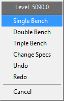
The current level displays at the top of the Level dialog box and it contains the following options:
Single Bench
Creates a berm at the nominated bench height.
Double Bench
Creates a berm at every second projection. For example, if the bench height was 10m, then a berm would be created at every 20m vertical increment. A projection string will be created at every bench height vertical increment.
Triple Bench
Creates a berm at every third projection. For example, if the bench height was 10m, then a berm would be created at every 30m vertical increment. A projection string will be created at every bench height vertical increment.
Change Specs
Displays the Change projection specs panel.
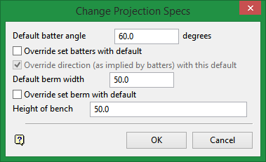
Use this panel to change the default batter angle, default berm width and bench height values. These values were originally set through the Automatic Projection 1 panel.
Undo
Removes the last operation.
Redo
Reinstates the last removed operation.
Cancel
Exits the option.
After each selection, the display is dynamically updated and the Level dialog box is redisplayed.

