Dump Design
Use the Dump Design option to conduct fast and simple dump design and planning. Through using this option, you will able to generate a solid that represents the dump, a new topography surface, and calculate the volume of the dump. You must provide an initial topography surface and a proposed "top or base" shape at the appropriate RL (Z level) for the dump, before being asked for the projection parameters. A solid model will then be built using the initial polygon projected at the nominated angle.
The resulting tonnage/volume displays in the Report Window. With this information, you can either modify the parameters or the polygon shape interactively until the dump is properly dimensioned.
Instructions
Click the Dump Design button
![]() on the Open Cut Design toolbar.
on the Open Cut Design toolbar.
or
On the Open Pit menu, point to Open Cut Design, and then click Dump Design to display the Dump Design Parameters panel.
The dump polygon selected should be flat. All vertices should have the same Z value, and it should be above or below the chosen surface triangulation. The polygon should not be registered to the surface.
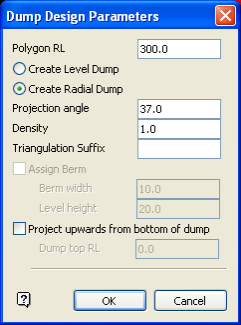
Polygon RL
The elevation of the polygon will be entered automatically. You can overwrite this value. You will also be able to change the elevation, by selecting the Edit Parameters option, if the dump volume doesn't meet your requirements.
Create Level Dump
Select this option to create a level dump.
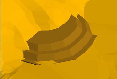
Diagram 1 - Level Dumps
Create Radial Dump
Select this option to create a radial dump. If this option is selected, then the Dump Design Modules panel displays once the Dump Design Parameters panel has been completed.
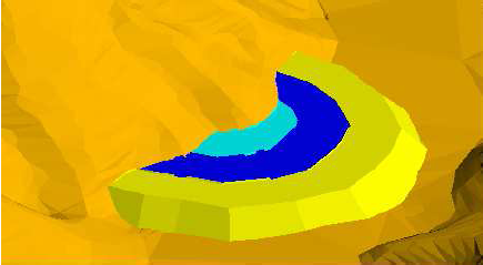
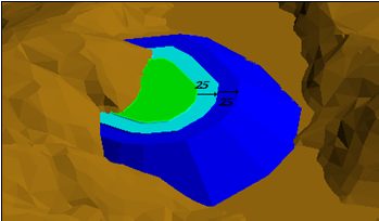
Diagram 2 - Radial Dumps
Projection angle
Enter the projection slope, in degrees, for the dump. 37° is a reasonable value for this angle.
Density
Enter the average density for the material that will be dumped.
Triangulation suffix
Enter a suffix which will be assigned to the triangulation file name. This field to create a unique triangulation file name. Specifying a triangulation suffix is optional.
Assign Berm
Select this check box to assign berms to the dump. You will need to enter the berm width and level height for dump. This check box will be disabled, that is, unavailable, if you have chosen to create radial dumps.
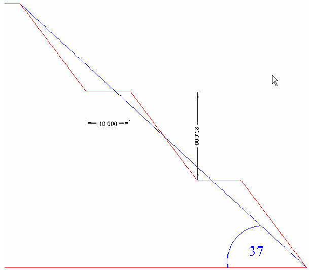
Diagram 3 - Berms assigned to a dump
Check the Shell triangulation along berm check box if you want to create a separate triangulation for each resulting berm. If this check box is not checked, then a single triangulation will be created instead.
Project upwards from bottom of dump
Select this check box to project a polygon upwards from the base of the waste. You will need to enter the elevation at which the base polygon will be projected.
Click OK.
Once selected, the Design dialog box displays. If you chose to create radial dumps, then the Dump Design Modules panel displays first.
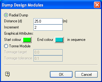
Radial Dump
Select this option to create a radial dump. You will need to specify the distance of the radial dumps (from the base dump) and the number of radial dumps. You will also need to select the colour sequence for the dumps.
Tonne Module
Select this option to create a new dump with a specified tonnage and tolerance. You will need to enter the tonnage target as well as the tolerance for the tonnage target value. For example, if the tonnage target is set to
'10000000.0'
, and the tolerance is set to
'100000.0
', then the option will create a dump between 9900000.0 and 10100000.0 tonnes.
Click OK.
Preview
Select this option to visualise the dump without saving the triangulation.
Interactive mode
Select this option to modify the original polygon or create a new dump with a specified tonnage. Select Digitise Mode to modify the original polygon. Once selected, you will be prompted to select the point that you want to move.
Select Target tonnage to create a new dump with a specified tonnage and tolerance. Once selected, the Target tonnage parameters panel displays.
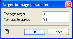
Enter in the target tonnage, then enter in the tolerance for the tonnage target value. For example if the target is set to 470000.0, and the tolerance is set to 10000.0, then the option will create a dump between 4,690,000 and 4,710,000 tonnes.
Modules
Select this option to divide the dump into parts. Once selected, the Dump Design Modules panel displays.
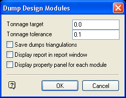
Specify the tonnage target and tolerance for each dump. Check the Save dumps triangulations check box to save each dump triangulation in the current working directory.
Check the Display report in report window check box if you want to display the results for each dump in the Report Window. Check the Display property panel for each module check box to specify how the triangulations should be displayed.
Save dump
Select this option to save the dump. Once selected, the Save enclosed volume panel displays.
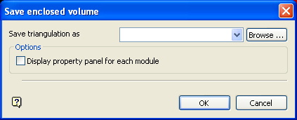
Enter the name for the resulting triangulation file. The list contains all triangulations in the current working directory. Click Browse to select a file from another location. Nominating an existing file will require you to confirm whether or not you want to overwrite the original information.
To create a new file, enter the file name and file extension.
Check the Display property panel for each module check box to specify how the triangulations should be displayed. Upon pressing the OK option, the standard Triangulation Properties panel displays. Refer to the Model > Triangle Utilities > Attributes option for information on the displayed panel.
Save polygons
Select this option to save the polygon in a nominated layer. Once selected, the Save border polygons panel displays.
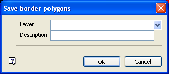
Select the layer that will be used to store the polygon. The available drop-down list contains the names of all loaded layers.
To create a new layer, enter the layer name. The layer name:
-
- may contain up to 40 characters.
- must begin with an alphanumeric character [0-9] or [a-z].
- cannot include spaces.
- can include hyphens [ - ], plus signs [ + ], underscores [ _ ], periods/dots [. ].
- can include the special characters of ÁÂÃÀÇÉÊÍÓÔÕÚÜÑ that are used in the Spanish and Portuguese languages.
Enter a description to further describe the contents of this layer. The description can be up to 80 alphanumeric characters and may include spaces. If a description is not entered, then a default description will be used instead. If the chosen layer already has an assigned description, the description displays when the layer is selected. Existing layer descriptions can be overwritten.
Save topography
Select this option to save the dump. Once selected, the Save new topography panel displays.
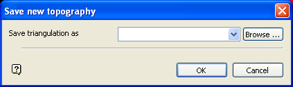
Enter the name for the resulting triangulation file. The list contains all triangulations in the current working directory. Click Browse to select a file from another location. Nominating an existing file will require you to confirm whether or not you want to overwrite the original information.
To create a new file, enter the file name and file extension.
To save a triangulation within an existing triangulation database, use the Browse button to locate the applicable '
.tri
' file. Once found, double-click on the file to display the Select Triangulation panel.
To replace an existing triangulation, click on the desired triangulation before clicking OK. To create a new a triangulation, enter the file name and file extension before clicking OK. Selecting an existing file will prompt you to confirm that you want to overwrite the file's original contents.
Change block
Select this option to recalculate the dump using a different polygon. Once selected, you will be prompted to select a polygon from the screen before being returned to the Dump Design Parameters panel.
Edit parameters
Select this option to return to the Dump Design Parameters panel.
Done
Select this option to exit the Dump Design option.
Once selected, a volume is produced and displayed in the Report Window.
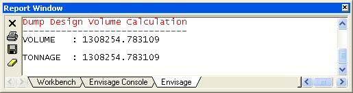
Diagram 5 - Report Window Output
A dialog box will also be displayed, allowing you to save the triangulation; select another dump polygon; move the vertices of the dump polygon; and alter the existing parameters.

