Assign Berm/Batter values
Use the Assign Berm/Batter values option to apply batter angles and berm widths to a pit or dump outline before projecting it.
The batter angles and berm widths can be assigned manually to selected line segments in the pit outline, or they can be applied from variables in an indexed block model. The batter angle is the inclination from horizontal of the pit wall between berms, not the overall slope angle of the pit. Batter angles may be varied around the pit perimeter and from one lift to the next.
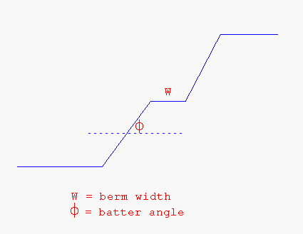
Diagram 1 - Batter Angle (Section View)
Berms, also known as "catch benches", are narrow (typically 2-10m or 6 to 33 feet wide) flat benches that must be incorporated into the sloping walls of any pit exceeding a specified depth (generally every 10-20m or 33 to 66 feet of pit depth). The width of these berms may need to be varied around the pit perimeter due to different geological conditions or other factors. This can be done with the manual method of nominating different berms to different sections (line segments) of the pit perimeter.
Variable batter angles and berm widths are stored in the W tag of the points in a perimeter string. The values apply to the segments following the point. The W-tag holds both the assigned projection angles and the berm distances in a 9 character number. The leading numerals hold the batter angle for projection, and the trailing numerals hold the berming distance, For example, W-tag of 450000010 implies an assigned batter angle for a projection of 45 degrees and an assigned berming width for berming of 10 metres. If only the batter angle is assigned, then the W-tag would read as 450000000. If only the berming width is assigned, then the W-tag would read as 10. Unassigned faces will have point W-tags of zero. With the block model method, each point in the perimeter will inherit batter and berm values from variables held at each position in the block model.
Note To use batter angles and berm widths from a block model, the model must be opened and indexed. It does not have to be displayed.
Instructions
Click the Assign Batter/Berm values button
 on the Open Cut Design and Ramps toolbars.
or
On the Open Pit menu, point to Open Cut Design, and then click Assign Berm/Batter values to display the Assign Batters and Berms panel.
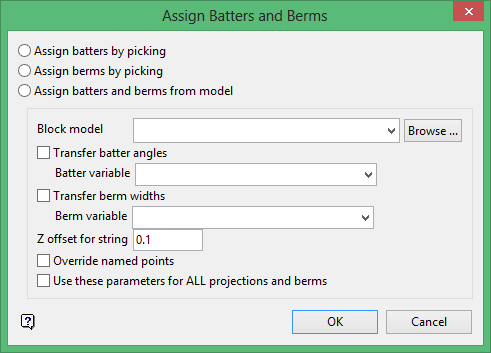
Assign batters by picking
Select this option to apply nominated batter angles to specific line segments. Any face not assigned a batter angle will have the default angle applied (see Project string option or, if using the Ramps module, then the Project string function in the Ramps > Design Pit/Dump option).
Assign berms by picking
Select this option to apply nominated berm widths to nominated line segments. Any face not assigned a berm width will have the default berm width applied (see Berm string option or, if using the Ramps module, then the Berm string function in the Ramps > Design Pit/Dump option).
Assign batters and berms from model
Select this option to use batter angles and berm widths stored in the currently open block model.
Specify the variables that hold the required batter angle and berm width. Each point in the string will be assigned the values from the block model cell into which the point falls.
Z offset for string
Enter an offset distance to change the Z coordinate where the block values will be read. A negative value means that the value will be read from a block located below the actual string elevation. Use an offset distance less than the Z block length.
Override named points
Select this check box to assign values from the block model to all points in the perimeter. If this check box is not checked, and batter angles and berm widths have been applied previously, then the values will be preserved. See also the notes on the W tag in the Overview section.
Use these parameters for ALL projections and berms
Select this check box to reassign batter angles and berm widths for each lift from the block model. If this check box is not checked, then the batters and berms are transferred from string to string as per the manual method.
Click OK.
The prompts and panels that are displayed depend on the assignment method chosen:
-
Manually assigning batter angles
-
Manually assigning berm widths
-
Using a block model
Manually assigning batter angles
Select the pit shape outline. Once selected, the chosen object is highlighted.
Select the start face (that is, line segment) to have a batter applied, followed by the end face. If the same batter is required for the entire pit, then select the face preceding (in digitised sequence) the start face.
Tip If the direction of digitising is not known, then use the Analyse > Label > Point Label option.
To apply different batter angles to separate sections of the outline, select the required end face for the first section as shown in Diagram 2. To apply a batter to just one face, select the same face as the start and end face.

Diagram 2 - Applying Batters to a Pit or Dump Outline
The following panel is then displayed.
Enter the batter angle. The angular units (either gradians or degrees) is set through the Miscellaneous section of the Tools > Preferences option. Any face that is not assigned a batter angle in this option will have the default angle applied (set in the Project string option or, if using the Ramps module, then the Project string function in the Ramps > Design Pit/Dump option).
Click OK.
You can then select another start and end face. The batter angle is saved as part of the W value assigned to each point in the pit outline. This can be checked by labelling the toe/crest string with the W tag value (refer to the Analyse > Label > Point Label option).
Click Cancel when you have finished selecting a start/end face. The pit/dump outline is then ready for projecting at the nominated batter angles.
The projection program (refer to the Project string option or, if using the Ramps module, then the Project string function in the Ramps > Design Pit/Dump option) projects the line segments of the wall outline rather than the individual points. Thus, there are no "transition" zones from one batter angle to another unless they are manually defined.
Where two adjacent segments of wall outline have different batter (projection) angles, each segment is projected at its nominated angle and the point of intersection is located. The two projected lines are then "relimited" to this point.
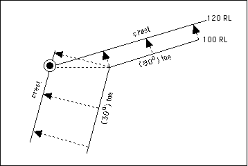
Diagram 3 - Projecting Up from Toe to Crest (Plan View)
Manually assigning berm widths
Select the pit shape outline. Once selected, the chosen object is highlighted.
Select the start face (that is, line segment) to have a berm applied followed by the end face. If the same berm is required for the entire pit, select the face preceding (in digitising sequence) the start face.
Tip If the direction of digitising is not know, then use the Analyse > Label > Point Label option.
To apply different berms to separate sections of the outline, select the required end face for the first section as shown in Diagram 4. To apply a berm to just one face, select the same face as the start and end face.
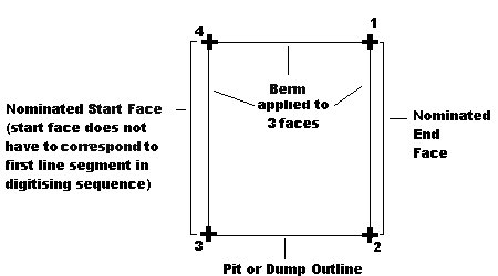
Diagram 4 - Applying Berms to a Pit or Dump Outline
The following panel is then displayed.
Enter the berm width. Any face that is not assigned a berm width in this option will have the default width assigned (set in the Berm string option or, if using the Ramps module, then the Berm string function in the Ramps > Design Pit/Dump option).
Click OK.
You can then select another start and end face. The berm width is saved as part of the W value assigned to each point in the pit outline. This can be checked by labelling the toe/crest string with the W tag value (refer to Analyse > Label > Point Label option).
Select Cancel when you have finished selecting a start/end face. The pit/dump outline is then ready for projecting at the nominated berm width.
Using a block model
To use batter angles and berm widths from a block model, the model must be open and indexed. It does not have to be displayed.
Berms and batters can be read from the block above or below by defining a value for the z offset for the string. If the offset is 1 then the berm and batter values will be read from blocks located 1 distance unit above the actual elevation of the string. If the offset is negative, then the batter and berm will be read from blocks located below the actual string elevation. If the offset is zero then unexpected results may occur when the string falls on the boundary between blocks.
The Multiple Selection box is then displayed. From this box, choose your method of selecting strings and select the strings.
Once selected, the chosen objects are shadowed and the berm widths and batter angles are applied. The berm widths and batter angles will be stored as part of the W value assigned to each point in the pit outline. This can be checked by labelling the toe/crest string with the W tag value (refer the Analyse > Label > Point Label option).

