Phase Generator
Use the Phase Generator option to automatically calculate the tonnage or profit from a block model. The resulting calculation can be saved in a nominated CSV file or a Microsoft Excel spreadsheet.
Prerequisites
- Current topography layer.
- Pushback design(s) intersected and clipped with topography. This includes an intersection polygon properly named.
- Ending elevation for each pushback for the number of specified periods.
Instructions
Click the Phase Generator button
![]() on the Open Cut Design toolbar.
on the Open Cut Design toolbar.
or
On the Open Pit menu, point to Open Cut Design, and then click Phase Generator to display the Phase Generator panel.
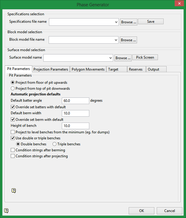
Specifications file name
Specify the name of the Phase Generator specification file (
.phs
) to use. The drop-down list contains all
.phs
files found in the current working directory. Click Browse to select a file from another location.
To create a new file, enter the file name and file extension.
Block model file name
Specify the block model that will be used in the calculations.
The drop-down list contains all block models found within the current working directory. Click Browse to select a file from another location.
Surface model file name
Specify the name of the surface model file that will be used for intersections purposes. The list contains all triangulations in the current working directory. Click Browse to select a file from another location. Use the Pick From Screen option if you want to select the surface directly from screen.
The Phase Generator panel also contains the following tabbed sections:Pit Parameters
Projection Parameters
Polygon Movements
Target
Reserves
Output
Pit Parameters tab
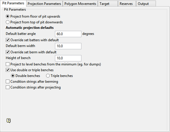
Specify whether to project the outline upwards or downwards. Use a clockwise string for a pit projection and an anticlockwise string for a projection.
Automatic projection faults
Default batter angle
Enter the default batter angle. This angle will be applied to faces that have not been assigned a batter angle (through using the Assign Berm/Batter values option).
Override set batters with default
Select this check box to replace all existing batter angles with the nominated batter angle. This option will override all batter angles, including the angles that were previously assigned.
For example, if you specify a default batter angle of '
60
', then all faces will be projected at 60° regardless of batter angles that have been assigned to the outline.
If this check box is not checked, then any previously assigned batter angle will be used in the projection. The nominated default value, however, will be used if a face has not been assigned a batter angle.
Default berm width
Enter the default berm width. This default value will be used for all faces that have not been assigned a berm width (through using the Assign Berm/Batter values option).
Override set berm with default
Select this check box to replace all existing berm widths with the nominated berm width.
For example, if you specify a default berm width of '
10.0
', then all faces will be projected 10 metres (33 feet) regardless of berm widths that have been assigned to the outline.
If this check box is not checked, then any previously assigned berm widths will be used in the projection. The nominated default value, however, will be used if a face has not been assigned a berm width.
Project to level from the minimum
Select this check box to create horizontal benches from variable Z outlines. This option is similar to using the "m" outline through the Project string option. If this check box is not checked, then each projected bench will retain the relative Z values of the nominated outline (similar to using the "r" outline through the Project string option).
Use double or triple benches
Select this check box to generate the pit with double bench or triple bench configuration.
Conditions strings after berming
Select this check box to condition the strings after berming.
Condition string after projections
Select this check box to condition the strings after projecting.
Refer to the Condition string option for more information on conditioning strings.Projection Parameters tab
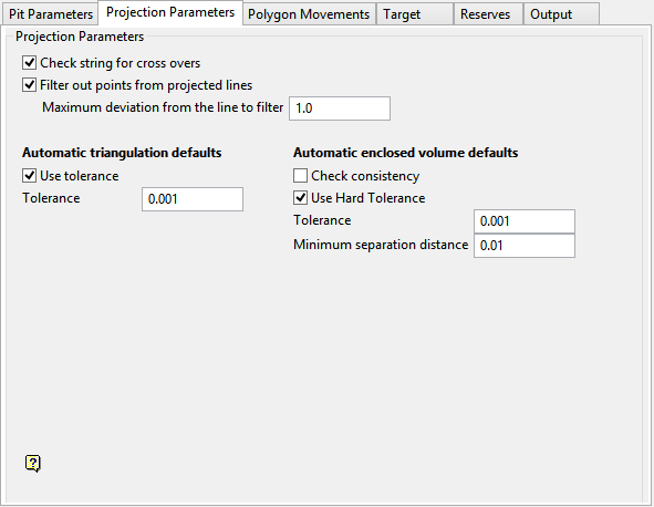
Check string for cross overs
Berming will cause an object to 'shrink' or 'grow'. As a result crossovers may occur, that is,, 'butterflies' can form at some corners. Select this check box to remove these crossovers.
Filter out points from projected lines
Select this check box to filter out points from the projected berms/projections to minimise the number of points in the new strings. You will need to specify the maximum deviation from the line to filter (the default value is '
1
').
Refer to the Filter option (under the Design > Object Edit submenu) for more information on filtering.
Use tolerance
Select this check box to use a tolerance. The nominated tolerance value will control the maximum distance that a triangulation node can be from a breakline before the breakline breaks adjacent triangles. The breakline tolerance stops the forming of long narrow triangles and helps to solve crossing breakline inconsistencies.
Use Hard Tolerance
Select this check box if you want to remove the small triangles that are usually created when you have high resolution (complicated) surfaces. You will need to enter a tolerance value (the default value is '
0.0010
'). If you use this option, it will delocate your triangulation solid by the value used (default value 0.001).
Minimum separation distance
Enter the minimum separation distance (in the unit of the window) allowed between the two surfaces.
Polygon Movements tab
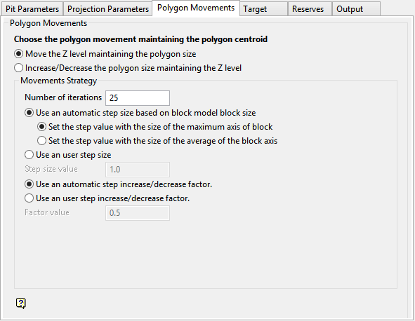
Move the Z level maintaining the polygon size
Select this option to change the level for each iteration.
Increase/Decrease the polygon size maintaining the Z level
Select this option to maintain the level but change the size maintaining the centroid.
Number of iterations
Enter the number iterations, this to stop the search.
Use a user step size
Enter the quantity in metres, each iteration uses this value for generating a new alternative.
Target tab
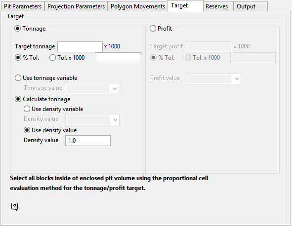
Tonnage
Select this option to incorporate a search by tonnage. You will need to specify the target or tolerance (as a percentage or total value).
Use a tonnage variable
Select this option when the tonnage block value has been previously evaluated. This will calculate by using a Full Cell Evaluation criteria.
Calculate tonnage
Select this option to calculate the tonnage by specifying the density variables and values.
Use density variable
Select this option to use a density stored in a block model variable to calculate the tonnage. Enter, or select from the drop-down list the density variable to use.
Use density value
Select this option to use a constant density value for each block in the model. Enter the constant density value.
Profit
Select this option to incorporate a search by profit. You will need to specify a target or tolerance (as a percentage or total value).
Profit Value
Select this option when the tonnage block value has previously been evaluated. This calculation will use a Proportional Cell Evaluation criteria. Enter, or select from the drop-down list the profit value.
Reserves tab
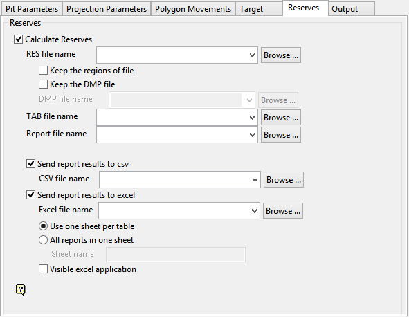
Calculate Reserves
Select this check box to calculate the reserves. You will need to specify the name of the reserves specification (
.res
) and report specification (
.tab
) files to be used, as well as the name of the resulting report file (
.rep
).
Send report to CSV
Select this check box to send the report to a nominated CSV file.
The drop-down list contains all
.csv
files found within your current working directory. Click Browse to select a file from another location.
To create a new file, enter the file name and file extension.
Send report to excel
Select this check box to send the report to a nominated Excel spreadsheet. The drop-down list contains all
.xls
files found in the current working directory. Click Browse to select a file from another location.
To create a new file, enter the file name and file extension.
Use one sheet per table
Select this option to store each table in a different sheet.
All reports in one sheet
Select this option to store all the reports in one sheet.
Visible excel application
Select this check box to open the spreadsheet in Excel upon generating the report.
Output tab
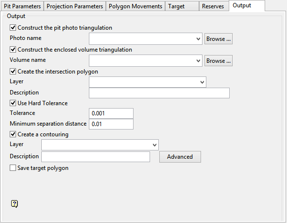
Construct the pit photo triangulation
Select this check box to generate a pit photo triangulation. The photo surface is a new topography that will be created by mining the new pit design.
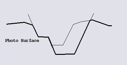
Diagram 1 - Pit Photo Triangulation
The list contains all triangulations in the current working directory. Click Browse to select a file from another location.
To create a new file, enter the file name and file extension.
Construct the enclosed volume triangulation
Select this check box to generate a enclosed volume triangulation. The enclosed volume is the solid formed by the pushback of the new pit into the previous topography.
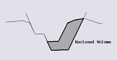
Diagram 2 - Enclosed Volume Triangulation
The list contains all triangulations in the current working directory. You can select a file from the list, select a file from another directory, or create a new file.
To save a triangulation within an existing triangulation database, use the Browse button to locate the applicable '
.tri
' file. Once found, double-click on the file to display the Select Triangulation panel.
To replace an existing triangulation, click on the desired triangulation before clicking OK. To create a new a triangulation, enter the file name and file extension before clicking OK. Selecting an existing file will prompt you to confirm that you want to overwrite the file's original contents.
Create the intersection polygon
Select this check box to generate a topography intersection polygon in a nominated layer.

