Update Toe
Use the Update Toe option to create advanced solids and lines in a simple and fast manner. These solids can be used to calculate reserves from a block model or to calculate volumes from a triangulation.
Instructions
Click the Update Toe button
![]() on the Open Cut Design toolbar.
on the Open Cut Design toolbar.
Or
On the Open Pit menu, point to Open Cut Design, and then click Update Toe.
This panel consists of the following tabs:
- Toe/Crest Expansion
- Result
- Report
Toe/Crest Expansion tab
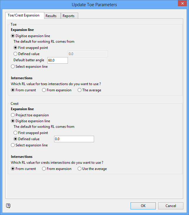
Toe
Expansion line
Digitise expansion line
Select this option to digitise the expansion line of the new toe. The default value for the working RL can either come from the elevation value of the first snapped point or from using a specified elevation value.
Default batter angle
Enter the default batter angle. This value will be used on faces on the new crest.
Select expansion line
Select this option to pick the new toe from an existing expansion line.
Intersections
The RL value for toe intersections can either come from the current RL value, the expansion line or from using the average RL value.
Crest
Expansion line
Project toe expansion
The documentation for this option has not yet been written.
Digitise expansion line
Select this option to digitise the expansion line of the new toe. The default value for the working RL can either come from the elevation value of the first snapped point or from using a specified elevation value.
Select expansion line
Select this option to pick the new toe from an existing expansion line.
Intersections
The RL value for toe intersections can either come from the current RL value, the expansion line or from using the average RL value.
Result tab
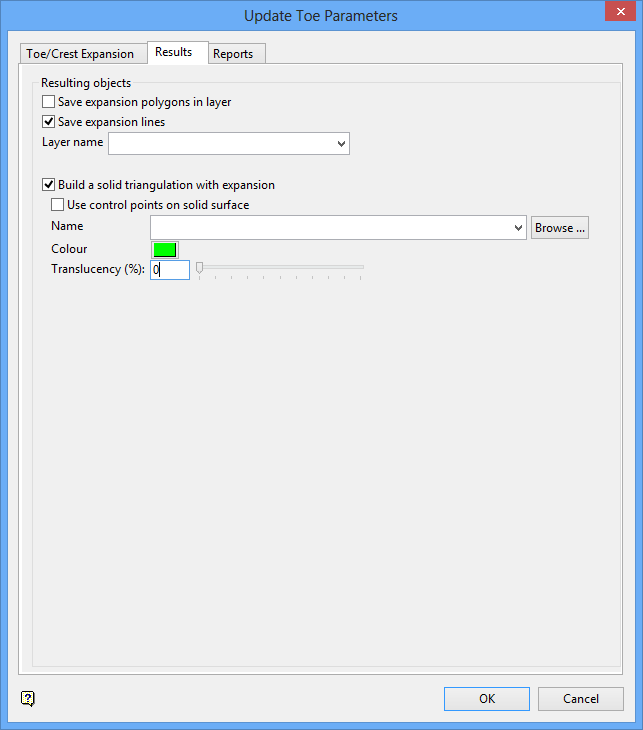
Resulting objects
Save expansion polygons in layer
Select this check box to save the resulting polygons in a nominated layer.
Save expansion lines
Select this check box to save the expansion lines in a nominated layer.
Layer name
Select the layer that will be used to store the expansion polygons and lines.
The drop-down list contains the names of all layers found within the currently open design database. If you select an existing layer, then the resulting data will be appended to the nominated layer. If you enter the name of an existing layer that is not currently loaded, then you will need to confirm whether you want to load the layer or replace it, i.e. overwrite its contents.
To create a new layer, enter the layer name. The layer name:
- may contain up to 40 characters.
- must begin with an alphanumeric character [0-9] or [a-z].
- cannot include spaces.
- can include hyphens [ - ], plus signs [ + ], underscores [ _ ], periods/dots [. ].
- can include the special characters of ÁÂÃÀÇÉÊÍÓÔÕÚÜÑ that are used in the Spanish and Portuguese languages.
Build a solid triangulation with expansion
Select this check box to build a triangulation along the expansion.
Use control points on a solid surface
Select this check box to create solid triangulations that follow the collars of each blasthole. If this check box is not checked, then a flat solid will be created for the wire frame and volume. It is necessary to have a layer which contains collars of blastholes or control points to use this option.
Name
Enter the name for the resulting triangulation file. The list contains all triangulations in the current working directory. Click Browse to select a file from another location. Selecting an existing file will prompt you to confirm that you want to overwrite the file's original contents.
To create a new file, enter the file name and file extension.
To save a triangulation within an existing triangulation database, use the Browse button to locate the applicable '
.tri
' file. Once found, double-click on the file to display the Select Triangulation panel.
To replace an existing triangulation, click on the desired triangulation before clicking OK. To create a new a triangulation, enter the file name and file extension before clicking OK. Selecting an existing file will prompt you to confirm that you want to overwrite the file's original contents.
Colour
Select a colour for the resulting triangulation.
Translucency (%)
Select this check box to apply a level of translucency to the resulting triangulation. When the slider is to the far left end, then the triangulation is solid therefore not translucent. When the slider is at the far right end, then the triangulation is fully translucent (invisible).
Alternatively, you can enter a translucency percentage, with '0' being solid and '100' being fully translucent.
Report tab
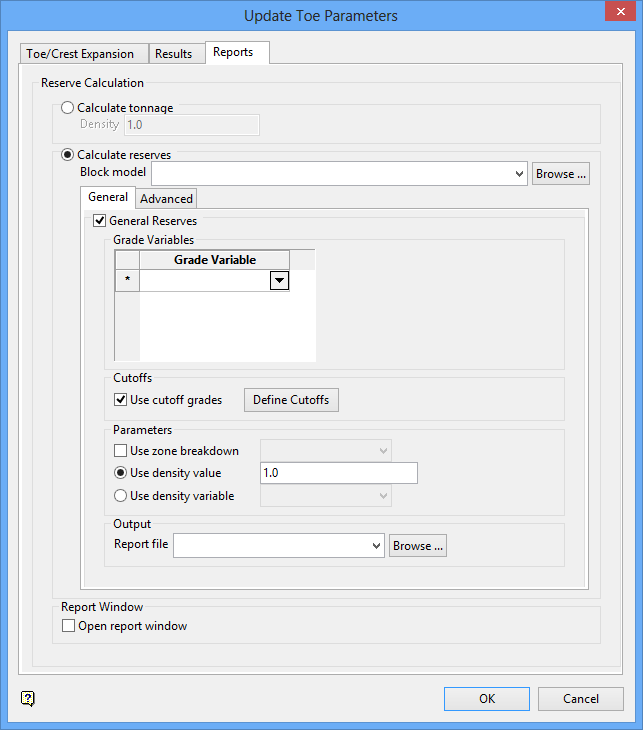
Reserve calculation
Calculate tonnage
Select this option to calculate the tonnage inside solid triangulations. You will need to enter the average density of the material.
Calculate reserves
Select this option to calculate reserves from a nominated block model file.
The drop-down list contains all block models found within the current working directory. Click Browse to select a file from another location.
Open report window
Select this check box to display the results in the Report Window.
This panel also contains the following two tabs, each of which are described in detail below.
- General
- Advanced
General tab
General Reserves
Select this check box to calculate reserves for grade variables using grade cutoffs.
Grade variables
Select the grade variables that will be used in the calculation (a maximum of 20 variables).
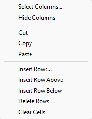
The panel utilises grid controls to manage the grid information, i.e. right-click context menus, that allow you to perform options such as hiding columns, cutting, copying, and pasting cells, and inserting and deleting rows. Right-click in the grid area to display the context menu. Descriptions of the available options are listed below.
-
Use the Select Columns option to choose which grid columns to display in the panel, and optionally save the selection to a template for future use. Alternatively, select cells and click Hide Columns to hide the respective columns directly.
-
Select cells and use the Cut, Copy, and Paste options to duplicate or move cell entries.
-
Select a cell in a row of interest and use the various insert and delete row options to manage the records in the grid.
-
Click Clear Cells to clear the contents of a selection.
Cutoffs
Use cut off grades
Select this check box to use cut off grades. Select the Define cutoffs option to display the Define cutoffs panel.
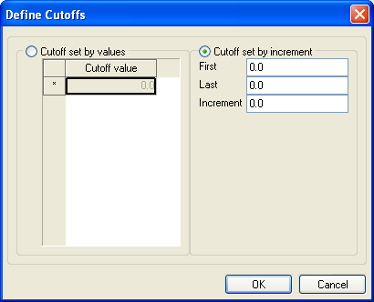
Cut off set by values
Select this option to cut off the grade variable at specific grade values. Up to 16 cutoff values can be specified.
Cut off set by increment
Select this option to cut off the grade variable at specific increments. You will need to specify the range as well as the increment value.
Parameters
Use zone breakdown
Select this check box to use a zone variable.
Use density value
Select this option to use a specific density value.
Use density variable
Select this option to use the value stored in a nominated grade variable. The drop-down list contains all variables found in the nominated block model.
Output
Report file
Specify the name of the report file (
.rep
) that will be used to store the resulting information.
The drop-down list contains all
.rep
files found within your current working directory. Click Browse to select a file from another location.
To create a new file, enter the file name and file extension.
Advanced tab

Advanced Reserves
Select this check box to calculate advanced reserves. You will need to nominate an existing reserves specification file (
.res
), an existing report specification file (
.tab
) and the name of the resulting report file (
.rep
). The appropriate files can either be selected from the drop-down lists or through using the Browse buttons.
To create a new report file, enter the file name and file extension. By default, the resulting file will be stored in the current working directory. Use the Browse option to select a different file location.
Note: Ensure that there are no regions in the nominated report specification file prior to running this option. You may need to edit the
.res
file (through a text editor) and delete any regions.
Click OK.
Select the start and end points of the insertion segment, then confirm that the correct segment has been selected.
Digitise the new toe string for the advanced. Ensure that the last point digitised is not the last point in the insertion segment.
Confirm whether to accept or reject the base string. If the Project toe expansion option (under the Toe/Crest Expansion tab) was selected, then the Bench Projection panel displays.

