Phase Design

Creating/ Expanding a pit from a pushback or phase to the final design
Use the Phase Design option to create a pit from a pushback or phase. You can also split a pit design into smaller pushback/ phases as they are mined. It is also possible to use this option to change the wall angles of a pushback and compare the difference in material gained or lost with the original pit.
Refer to the Phase Design Step-by-Step section for an example on how to use the Phase Design option.
The Phase Design option can also be accessed by selecting the
![]() Phase Design button from the Phase Design toolbar.
Phase Design button from the Phase Design toolbar.
Instructions
- Select Open Pit menu
- Select Phase Design submenu
- Select Phase Design option
The following panel displays.
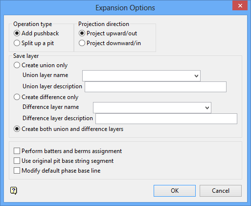
Expansion Options panel
Operation type
Add Pushback
Select this option to add a phase/ pushback to the original pit.
Split up a pit
Select this option to break an existing pit into smaller pushback/phases.
Projection direction
Project upward/out
Select this option to project a polygon/line using a toe string as the starting string.
Project downwards/in
Select this option to project a polygon/line using a crest string as the starting string.
Save layer
Create union only
Select this option to save the layer that contains the expanded or split up pit. You will need to specify the name of the layer.
To create a new layer, enter the layer name. The layer name:
- may contain up to 40 characters.
- must begin with an alphanumeric character [0-9] or [a-z].
- cannot include spaces.
- can include hyphens [ - ], plus signs [ + ], underscores [ _ ], periods/dots [. ].
- can include the special characters of ÁÂÃÀÇÉÊÍÓÔÕÚÜÑ that are used in the Spanish and Portuguese languages.
Create difference only
Select this option to save the layer that contains the pushback strings. You will need to specify the name of the layer.
To create a new layer, enter the layer name. The layer name:
- may contain up to 40 characters.
- must begin with an alphanumeric character [0-9] or [a-z].
- cannot include spaces.
- can include hyphens [ - ], plus signs [ + ], underscores [ _ ], periods/dots [. ].
- can include the special characters of ÁÂÃÀÇÉÊÍÓÔÕÚÜÑ that are used in the Spanish and Portuguese languages.
A layer description can be applied to either layer. Layer descriptions can contain up to 80 alphanumeric characters (spaces are allowed). If a description is not entered, then the default "
Created layer <date><time>
" will be used instead. If the chosen layer already has an assigned description, then this will be displayed when the layer is selected. Existing layer descriptions can be overwritten.
Create both union and difference layers
Select this option to save both the union and difference layers. You will need to specify the names of the layers in the Union layer name and Difference layer name fields.
Perform batters and berms assignment
Select this option to assign batters and/or berms. The Assign Batters and Berms panel displays once the base string has been selected. Refer to the Assign Berm/Batter values option for information on this panel.
Use original pit base string segment
Select this option to change the wall angle, which will result in a new pushback. This option is useful to see how much material is gained or lost from making the walls steeper or shallower. The Automatic Pit panel displays once the base string has been selected. Thus you can alter the angle of the pushback. Refer to Auto Pit for more information of this panel.
Modify default phase base line
Select this option to change the point location of the digitised base string. Once the base string has been digitised, you are prompted to select points in the string to move.
Select OK.
Select the toe string to use as the base string. Confirm that you have selected the correct object.
The cursor changes to
![]() Snap to Points mode. Select the start and end points of the insertion segment. Confirm that the correct segment was selected.
Snap to Points mode. Select the start and end points of the insertion segment. Confirm that the correct segment was selected.
Digitise the new base string for the pushback. Do not digitise the last point past the last point in the insertion segment. Also it is not necessary to snap the last digitised point to the last point in the insertion segment - the program does this automatically once you right-click to cancel digitising the base string. Accept or Reject the base string.
The Phase Projection Set Up panel is then displayed.
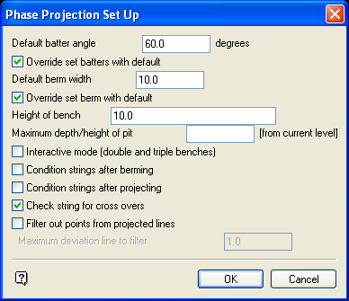
Phase Project Set Up panel
This panel is the same as the Automatic Projection panel in Auto Pit . Ensure that the Height of Bench is the same as for the original pit and that the Maximum depth/height of Pit is past the highest string on the original pit.
Select OK.
The pit is projected or split. Use the
![]() Save button on the Standard toolbar to save the layers. You can then use the
Save button on the Standard toolbar to save the layers. You can then use the
![]() Remove Layer button to clear the original pit, so you can observe the results of the projection.
Remove Layer button to clear the original pit, so you can observe the results of the projection.

