Create Strips and Blocks
Create Mine Strips and Blocks
The Create Strips and Blocks option to design mine strips and/or blocks along a nominated line or polygon. This forms the basis for strip and block reserves calculations.
Use the Fan Strips option to create mine strips that follow a pit turn or fan layout.
Instructions
- Select Open Pit menu
- Select Pit Layout menu
- Select Create Strips and Blocks option
The following panel displays.
Strip and Block Layout panel
Specifications
Specification name
Select the
.sb_spec
specification file to load. The drop-down list displays all available.sb_spec files found in your current working directory. Click Browse to select a file from another location. Type in a name to create a new specification file.
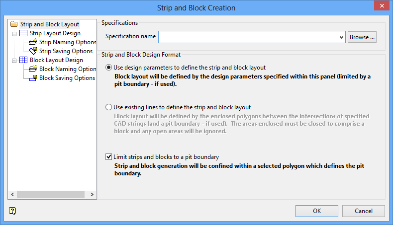
Strip and Block Design Format
Use the option buttons to select the method for defining the strip and block layout.
Use design parameters to define the strip and block layout
Select this option to use the design parameters in the Strip Layout Design and Block Layout Design branches of this panel to define the design parameters.
Use existing lines to define the strip and block layout
Select this option to use existing cad strings on the screen for the design parameters for the strips and blocks. The Strip Layout Design and Block Layout Design branches will not be available when using this option.
Limit strips and block to a pit boundary
Select this check box to design strips and/or blocks in a nominated polygon. The nominated polygon will define the extent of the strips and blocks. A straight line will also be used as a baseline against which the strips and blocks will be generated. It does not matter where the line lies with respect to the pit outline, as it is only used for the orientation of the strips and blocks. If this check box is not selected, then the resulting strips and/or blocks will be generated along a nominated base line.
Select the Strip Layout Design option. The following panel displays.
Strip and Block Layout - Strip Layout Design panel
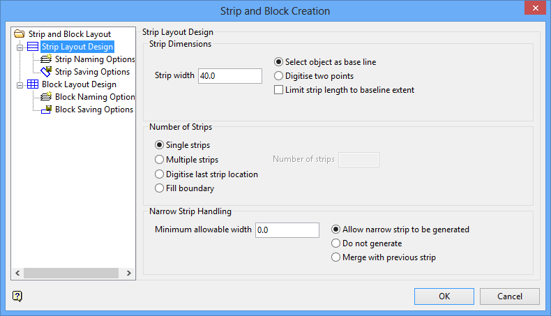
Strip Dimensions
The Use design parameters to define the strip and block layout option must have been selected from Strip and Block Layout panel for these fields to be available.
Strip width
Enter the width of each strip that will be generated.
Select object as base line
Select this option if you have an existing cad line on the screen that you want to use as the base line for the strips.
Digitise two points
Select this option if you have no cad data to define the strip base line. You will be prompted to indicate the baseline by digitising two points on the screen.
Limit strip length to baseline extent
This content is being developed.
Number of Strips
Single strips
Select this option to draw a single strip.
Multiple strips
Select this option to draw more than one strip. You will also need to indicate to Number of strips you would like to be drawn.
Digitise last strip location
Select this option to digitise, on the screen, the approximate location where you want the strips to finish.
Fill boundary
Select this option to draw strips and blocks to fill the boundary.
Narrow Strip Handling
The Limit strips and block to a pit boundary check box must be selected for these options to be available.
Minimum acceptable area
Enter the minimum acceptable area. Strips less than the specified area will not be created. Use the default value of '
0.0
' if you don't want to apply a restriction.
Allow narrow strip to be generated
Select this option to allow very narrow strips to be generated. All strips will be created, regardless of their width.
Do not generate
Select this option to not generate strips if they are more narrow than the minimum allowable strip width.
Merge with previous strip
Select this option to merge strips that are more narrow than the minimum allowable strip width with the previous strip.
Select the Strip Naming Options option. The following panel displays.
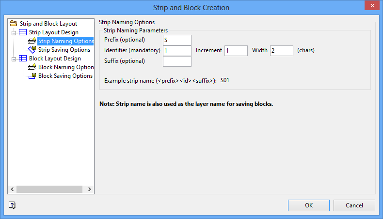
Strip and Block Layout - Strip Naming Options panel
Strip Naming Parameters
The fields in this section are used to select the method for defining the strip and block layout.
Prefix
Enter the desired content to be placed in front of the strip number.
Identifier
Enter the starting number for the strip numbering scheme. You will also need to indicate the Increment, and Width (in characters).
Suffix
Enter the desired content to be placed after the strip number.
Select the Strip Saving Options option. The following panel displays.
Strip and Block Layout - Strip Saving Options panel
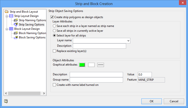
Strip Object Saving Options
This section to specify into which layers the strips will be saved.
Create strip polygons as design objects
Select this check box to save the strips as objects in a layer.
Layer Attributes
This section sets the layer naming for the strips.
Save each strip in a layer named as strip name
Select this option to create a separate layer for each strip. The name of the layer will be the same as the strip name.
Save all strips in currently active layer
Select this option to save all layers into the current layer in Vulcan.
Select layer for all strips
Select this option to enter a layer name into which all strips will be saved. You will also need to select the desired Layer name entry from the drop-down box. This check box is populated by the current working directory. Type in the desired name to create a new layer. Additionally, you may enter a Description for the layer using up to 40 alphanumeric characters
Replace existing layer(s)
Select this check box to replace any existing layers.
Object Attributes
This section sets up the graphical attributes and descriptions that will be used for the strips.
Graphical attributes
Select the colour, pattern, and line style using the buttons.
Description
Enter the object description for the strips.
Value
Enter the object value for the strips.
Group name
Enter the group name for the object.
Feature
This field is automatically populated.
Create with name label turned on
Select this check box to have the labels displayed on the screen when the objects are created.
Select the Block Layout Design option. The following panel displays.
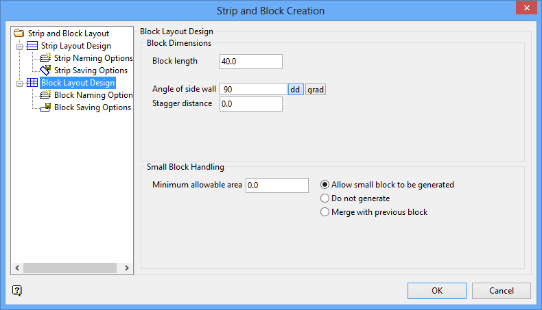
Strip and Block Layout - Block Layout Design panel
Block Dimensions
The Use design parameters to define the strip and block layout option must have been selected from Strip and Block Layout panel for these fields to be available.
Block length
Enter the length of each block that will be generated.
Angle of side wall
Enter the angle in decimal degrees (dd) or gradians (grad). Ensure the corresponding option (dd or grad) is selected for the entry. For example, an angle of 90 dd will create side walls that are perpendicular to the strip base line.
Stagger distance
Enter the distance by which the blocks in adjacent strips are staggered. Note if the stagger distance is greater than zero, the length of the first block will be reduced by the length of the stagger.
Small Block Handling
This section to control what Vulcan will do when small blocks are generated.
Minimum allowable area
Enter the minimum acceptable area. Blocks that are smaller in area than the minimum indicated will be handled by the selected option below. Use the default value of '
0.0
' if you don't want to apply a restriction.
Allow small block to be generated
Select this option to generate the small blocks.
Do not generate
Select this option to not generate any blocks that fall below the minimum allowable area.
Merge with previous block
Select this option to merge any blocks that are less than the minimum allowable area with the previous block.
Select the Block Naming Options option. The following panel displays.
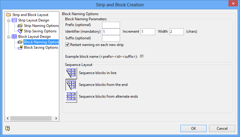
Strip and Block Layout - Block Naming Options panel
Block Naming Options
Block Naming Parameters
The fields in this section are used to set how the blocks will be named.
Prefix
Enter the desired content to be placed in front of the block number.
Identifier
Enter the starting number for the blocks numbering scheme. You will also need to indicate the Increment, and Width (in characters).
Suffix
Enter the desired content to be placed after the block names.
Restart naming on each new strip
Select this check box to restart the block numbering on each new strip.
Note If Batvol is to be used for reserving, the block names must be numerical and may only contain a maximum of three characters.
Sequence Layout
Sequence blocks in line
Select this option to keep all block numbers lined up across the strips. Note some strips may not start with block number 1.
Sequence blocks from the end
Select this option to have the first block always be named number one [ 1 ].
Sequence blocks from alternate ends
Select this option to start the naming of the blocks from alternate ends.
Select the Block Saving Options option. The following panel displays.
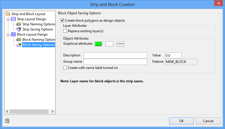
Strip and Block Layout - Block Saving Options panel
Block Object Saving Options
This section to specify into which layers the blocks will be saved.
Create block polygons as design objects
Select this check box to save all blocks as design objects in a layer. Note if this check box is not selected, no blocks will be created.
Layer Attributes
This section sets the layer naming for the blocks.
Replace existing layer(s)
Select this check box to replace any existing layers.
Note: See the note at the bottom of the panel that states the layer name for the block objects is the strip name.
Object Attributes
This section sets up the graphical attributes and descriptions to be used for the blocks.
Graphical attributes
Select the colour, pattern, and line style using the buttons.
Description
Enter the object descriptions for the blocks.
Value
Enter the object value for the blocks.
Group name
Enter the object group name for the blocks.
Feature
This field is automatically populated.
Create with name label turned on
Select this check box to have the block names displayed after the blocks have been created.
Click OK.
The following prompts depend upon whether you have chosen to generate the mine strips and/or blocks using a nominated pit outline or base line.
Creating mine strips and blocks in a nominated pit outline
Select the pit outline (that is, an existing polygon), followed by the line parallel to the main block. The selected line will be used to determine the orientation of the strips and blocks. The elevation of the nominated pit outline will be assigned to the resulting strips and blocks.
The strips and blocks are then created and highlighted. You will then be asked to confirm that these are the correct blocks. Incorrect returns you to the Strip/Block Generation panel. Correct blocks results in the strips and blocks being saved.
Each strip will be saved as an individual layer, and each block as an individual object in its strip. The names for the resulting strips and blocks are determined by the parameters specified through the Strip/Block Generation panel.
Once confirmed, you will be returned to the Strip/Block Generation panel. Click Cancel to exit the option.
Creating mine strips and blocks along a nominated base line
Indicate the first point on the base line, followed by the second point. The second point is used to determine the approximate limit of the strips. Any of the Snap modes (
 Indicate,
 Snap to Grid,
 Snap to line or
 Snap to point ) can be used to snap anywhere along the baseline. Refer to the Digitise toolbar for details on these modes. If
 Indicate mode is used, and the current Z value differs from the Z values of the baseline, then the strips are generated at the level of the current Z value, not the baseline.
If the nominated block size does not divide equally along the line defined by the two points, then the final block will extend beyond the second point, rather than fall short.
Note: Once the strips/blocks are generated, they will lie on the 'left hand side' of the baseline, so you will need to select the appropriate end of the baseline.
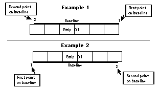
Diagram 1 - Baseline
As shown in the Diagram 2, the naming and numbering proceeds incrementally, beginning with the names and numbers entered in the Strip/Block Generation panel.
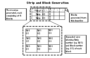
Diagram 2 - Strip and Block Generation
Once the second point has been indicated, the first strip and blocks are created and you will be asked whether to generate the next strip, change the parameters or finish generating strips.
Each strip will be created as a separate layer (
<prefix><number>
) and each block will be created as a separate object (
<number>
) in its strip layer. Once you have finished generating the strips, you will be returned to the Strip/Block Generation panel.
Click Cancel to exit the option.

