Offset Strips
Create Parallel Mine Strips
The Offset Strips option to generate parallel mine strips that are offset from a baseline and, if required, limited by a nominated polygon. Both the baseline and, if applicable, the polygon must already exist before using this option.
Instructions
- Select Open Pit menu
- Select Pit Layout submenu
- Select Offset Strips option
The following panel displays.
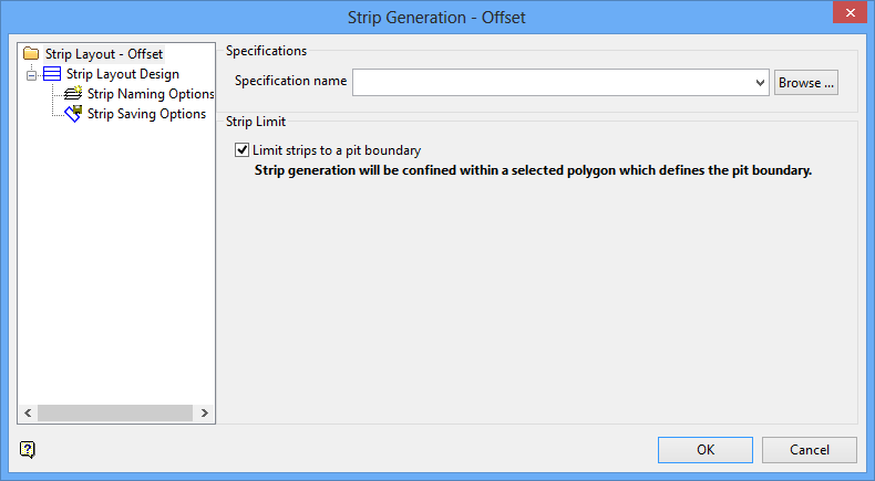
Strip Layout, Offset panel
Specifications
Specification name
Select the
.sb_spec
specification file to load. The drop-down list displays all available
.sb_spec
files found in the current working directory. Click Browse to select a file from another location. Type in a name to create a new specification file.
Strip Limit
Limit strips to a pit boundary
Check this check box to confine the strip generation in a selected polygon, which defines the pit boundary.
Click Strip Layout Design. The following panel displays.
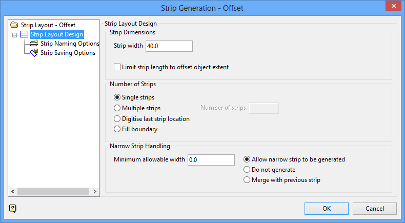
Strip Layout, Offset - Strip Layout Design panel
Strip Layout Design
Strip Dimensions
Strip Width
Enter the strip width.
Limit strip length to offset object extent
Check this check box to limit the length of the strips to the offset object extent, to be the same length as the offsetting object.
Number of Strips
Single Strips
Select this option to create just one [ 1 ] strip.
Multiple Strips
Select this option to create multiple strips. You will also need to enter the Number of strips desired.
Digitise last strip location
Select this option to digitise, on the screen, the location of the last strip to be created.
Fill boundary
Select this option to create as many strips as necessary to fill to the boundary polygon.
Narrow Strip Handling
Minimum allowable width
Enter the minimum allowable strip width.
Allow narrow strip to be generated
Select this option to allow very narrow strips to be generated. All strips will be created, regardless of their width.
Do not generate
Select this option to not generate strips if they are more narrow than the minimum allowable strip width.
Merge with previous strip
Select this option to merge strips that are more narrow than the minimum allowable strip width with the previous strip.
Click Strip Naming Options. The following panel displays.
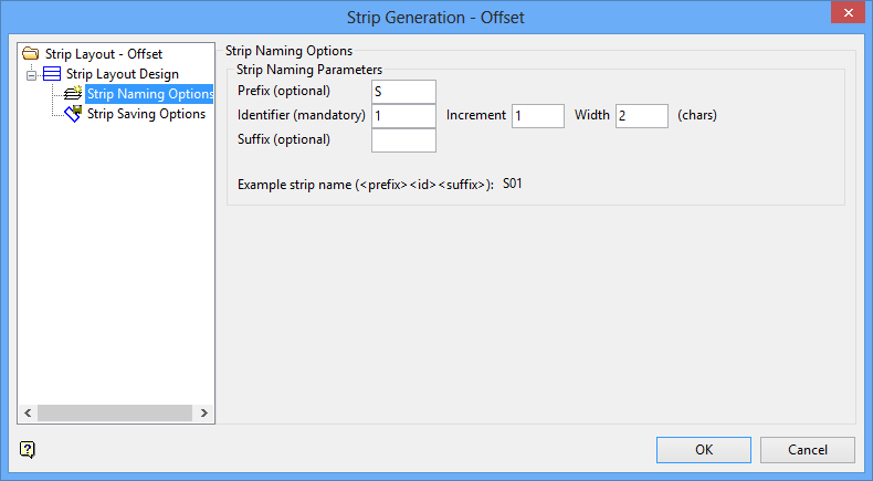
Strip Layout, Offset - Strip Naming Options panel
Strip Naming Options
Strip Naming Parameters
The fields in this section are used to select the method for defining the strip and block layout.
Prefix (optional)
Enter the desired content to be placed in front of the strip numbers, up to a maximum of 10 characters.
Identifier (mandatory)
Enter the starting number for the strip numbering scheme. You will also need to identify the Increment and Width, in characters.
Suffix (optional)
Enter the desired content to be placed after the strip number, up to a maximum of 10 characters.
Click Strip Saving Options. The following panel displays.
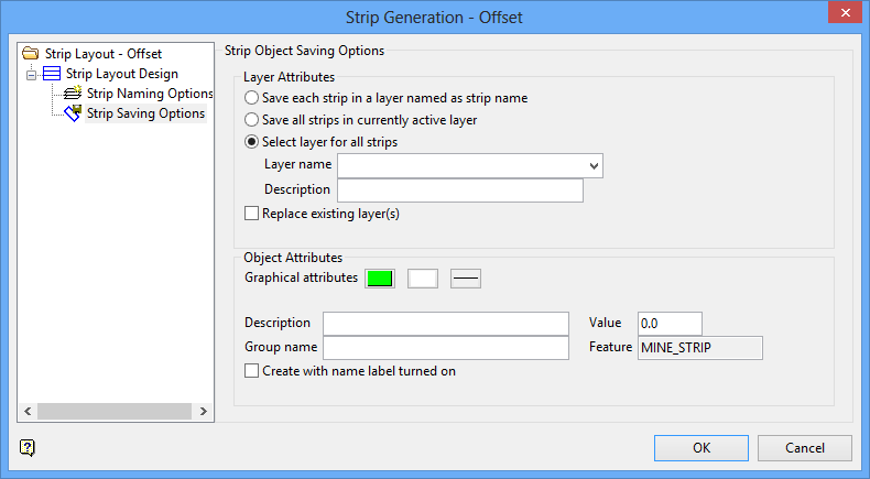
Strip Layout, Offset - Strip Saving Options panel
Strip Object Saving Options
Layer Attributes
Save each strip in a layer named as strip name
Select this option to create a separate layer for each strip. The name of the layer will be the same as the strip name.
Save all strips in currently active layer
Select this option to save all layers into the current layer in Vulcan.
Select layer for all strips
Select this option to enter a layer name into which all strips will be saved. You will also need to select the desired Layer name entry from the drop-down box. This box is populated by the current working directory. Type in the desired name to create a new layer. Additionally, you may enter a Description for the layer using up to 40 alphanumeric characters.
Replace existing layer
Check this check box to replace any existing layers.
Object Attributes
Graphical attributes
Select the desired entry from the Colour, Pattern, and Line buttons.
Description
Enter the object description.
Value
Enter the object value.
Group name
Enter the group name for the object.
Feature
This field will automatically be populated.
Create with name label turned on
Check this check box to have the labels displayed on the screen when the objects are created.
Offset Options
The baseline may be a portion of a selected line or the whole selected line.
Limit strips to pit boundary
Select this check box if you want to limit the strips. If this checkbox is not ticked, then the strips will be offset against the baseline.
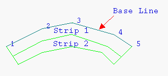
Diagram 1 - Generating Strips Against a Baseline
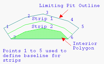
Diagram 2 - Generating Strips Within a Limiting Polygon
Offset portion of selected line
Select this option to use a portion of a string. Once this panel has been completed, you will be prompted to select the start and end points of the baseline. If the two points are on a closed polygon, then you will be required to indicate the part of the polygon to use.
Note: If you have chosen to use a limiting polygon, that is, you have enabled the Limit strips to pit boundary check box, then you can use part of that polygon as the baseline.
Offset whole of selected line
Select this option to use an entire string. Once this panel has been completed, you will be prompted to select the offset object, that is, the string.
Offset
Enter the required width of the strips.
Number of strips
Enter the total number of strips to be generated in the first pass. Once these strips have been generated, you will have the opportunity to generate the same number of adjacent strips using the same parameters or to exit the option.
Digitise last strip location
Select this check box to indicate the approximate location of the last strip rather than explicitly indicating the number of strips to create (through the Number of strips field). If this check box is checked, then the Number of strips field will be disabled, that is, unavailable, and you will be required to indicate the location of the last strip upon completing the Strip Generation panel.
Filtering minimum distance
Enter the minimum distance. This value allows you to delete duplicate or excess points from the offsetting string or polygon that are at a distance (between points) less than the one specified.
Filtering minimum deviation
Enter the minimum angle. This value allows you to delete duplicate or excess points from the offsetting string or polygon that are at an angle less than the one specified.
Strip Names
Layer Options
The strips can be saved in separate layers, in a selected layer or in a new layer.
Save strips in separate layers
Select this option to save the strips in separate layers. Each layer name will be of the format
<prefix><number>
. See also Start strip number.
Save strips in selected layer
Select this option to save the strips in the same layer as the baseline.
Save strings in new layer
Select this option to save the strips within a nominated layer.
Replace layer if already exists
Select this check box if you want to overwrite the contents of the selected layer. If this checkbox is not ticked, then the resulting strips will be appended to the chosen layer.
Strip name template
Each strip is created as a separate layer. The name assigned to each layer will be the name of the strip it contains.
Strip name, which can be up to 40 alphanumeric characters in length, are specified with a template of the form:
PREFIX%.NDSUFFIX
where
PREFIX
and
SUFFIX
are optional.
%.ND
is used to specify the number of characters on an incremented integer.
| Strip Name | Result |
| STP%.D | STP1, STP2, STP3,... |
| %.D | 1, 2, 3,... |
| S%.2D | S01, S02, S03,... |
Strip width
Enter the width of each strip that will be generated.
Start strip number
Enter the starting number for the strip layer.
Example:
Strip name template: S%.2D Strip number increment: 2 Start strip number: 10
Result:
S10 S12 S14 etc.
Strip number increment
This is used in the strip layer name. Each layer name will be incremented with the number specified here.
For example, if the template is '
S%.2D
', and the increment is set to '
2
', then the resulting layers will be named
S01
,
S03
,
S05
etc.
Select OK.
Select the object (baseline) that want you to offset. The baseline can intersect the polygon (as shown in Diagram 3), or be entirely outside it (as shown in Diagram 4). If you checked the Limit strips to pit boundary check box, then you will be prompted to select the limiting object first.
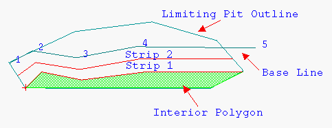
Diagram 3 - Baseline Intersecting the Polygon
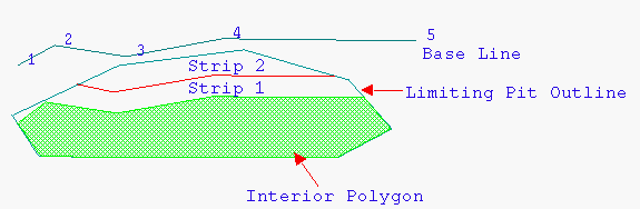
Diagram 4 - Baseline Outside the Polygon
If you selected the Offset whole of selected line option, then the first strips are generated and you will be asked whether to retain or reject the strips.
If you selected the Offset portion of selected line option, then you will be required to define that baseline by selecting the first and last points of the base line. If you are using an open string to define the baseline, as in Diagram 1 (compared to a closed polygon), then the first strips will be generated and you will be asked whether or not to retain or reject the strips. If you are using a closed polygon to define the baseline, then you will be required to select the string of interest.
For example: If you are using a portion of a closed polygon, then you are effectively splitting the polygon into two strings in selecting the start and end point of the baseline. Because both of these portions may be available to be used as a baseline, you need to select the string of interest.
If you checked the Digitise last strip location check box, then you will need to indicate the approximate location of the last strip before the strips can be generated. Once the location has been selected, the strips are generated and you will be asked whether to retain or reject the strips.
Note: If you selected the Limit strips to pit boundary check box, and you did not generate strips all the way across the polygon, then you will be prompted as to whether or not you want to create an interior polygon in the remaining area. This polygon can in turn be used to generate further strips with completely different parameters and baseline.

