Solid Ramps
The Solid Ramps option to generate a solid ramp in a nominated bench. The Solid Ramp option will result in the creation of two triangulation files, as well as a layer that will store the ramp polygons.
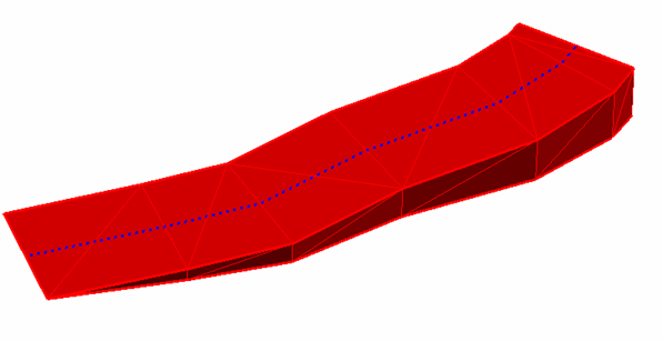
Figure 1 : A Generated Ramp
Instructions
On the Open Pit menu, point to Ramps, then click Solid Ramps to display the following interface.
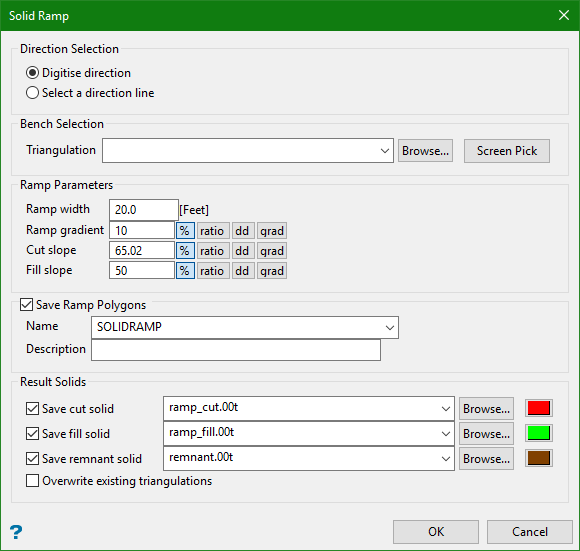
Direction selection
Digitise direction
Select this option to digitise the ramp's direction onscreen.
Select a direction with line
Select this option if you want the ramp's direction to be defined through using an existing line object. The line object must be loaded onto the screen prior to running the Solid Ramp option.
Bench selection
The base solid can either be selected directly from the screen or through browsing your data directories. The list contains all triangulations in the current working directory. Click Browse to select a file from another location.
Ramp parameters
Ramp width
Enter the width of the ramp.
Ramp gradient
Enter the grade of the ramp.
Note: The value can be entered as a percentage, a ratio, decimal degrees or gradians.
Example: To enter a value of 50%, select the  option and enter
 50. Select a different angle format option to convert a value.
Cut slope
Enter the slope grade.
Fill slope
Enter the fill grade.
Save ramp polygons
Select this check box to save the polygons in a nominated layer (the default layer is SOLIDRAMP ).
The drop-down list contains the names of all layers found within the currently open design database. If you select an existing layer, then the resulting data will be appended to the nominated layer. If you enter the name of an existing layer that is not currently loaded, then you will need to confirm whether you want to load the layer or replace it, i.e. overwrite its contents.
Layer name
Select a layer from the drop-down list, or enter a name for a new layer. The name of the new layer:
-
may contain up to 40 characters,
-
must begin with an alphanumeric character [0-9] or [a-z],
-
cannot include spaces,
-
can include hyphens [ - ], plus signs [ + ], underscores [ _ ], periods/dots [. ],
-
can include the special characters of ÁÂÃÀÇÉÊÍÓÔÕÚÜÑ that are used in the Spanish and Portuguese languages.
Layer descriptions, which are optional, can consist of 80 alphanumeric characters (spaces are allowed).
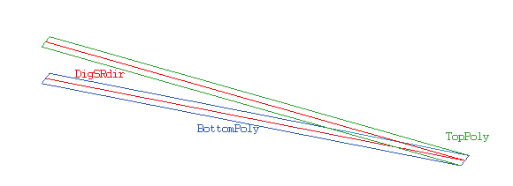
Figure 2 : Saved Objects
The digitised and projected polygon lines will be assigned the DigSRdir object names, while the top and bottom polygons will be named TopPoly and BottomPoly respectively.
Save cut solid
Select this check box to save the triangulation file that represents the cut portion of the ramp.
The list contains all triangulations in the current working directory. Click Browse to select a file from another location. Selecting an existing file will prompt you to confirm that you want to overwrite the file's original contents.
To create a new file - Enter the file name and file extension.
To save a triangulation within an existing triangulation database - Use the Browse button to locate the applicable (.tri) file. Once found, double-click on the file to display the Select Triangulation panel.
To replace an existing triangulation - Click on the desired triangulation before clicking OK. To create a new a triangulation, enter the file name and file extension before clicking OK.Selecting an existing file will prompt you to confirm that you want to overwrite the file's original contents.
Save fill solid
Select this check box to save the triangulation file that represents the fill portion of the ramp.
Save remnant solid
Select this check box to save the triangulation file that represents the bench.
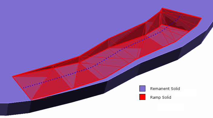
Figure 3 : The Resulting Solids
Overwrite existing triangulations
Select this option to overwrite triangulations with the same name as those entered above.

