Cut & Fill
Calculate Cut and Fill Volumes
The Cut & Fill option allows cut and fill polygons to be generated between the template (refer to the Template option) and a chosen line string. The polygons are defined as being any enclosed polygon formed through the intersection of the template and the chosen line string.
The total cut area, total fill area, and the difference between the areas is reported in the Report Window of Vulcan.
When all required sections have been completed, the C&F Volume option can be used to give a report of end area cut and fill volumes.
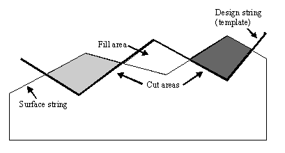
Figure 1 : Cut/Fill Areas
Note: This option requires you to be in Section view. If you are in Plan view, then you will be passed through the Section View option first.
Instructions
- Select Open Pit menu
- Select Section Design submenu
- Select Cut & Fill option
The Select dialog box displays. This dialog box contains the following options:
Place template
Allows the template to be placed in an exact position in the section window. You will be asked to select the original surface string (the string that represents the old surface in section). The program will then calculate the cut and fill polygons and, if any, temporarily display them. For the first calculation, the current template position will be used. Subsequent calculations use the indicated template position (see below).
You will be asked whether or not to keep the design (that is, template position). If you keep the design, then the polygons are formed. If you reject the design, then you can place the template in a new position and you will be prompted to select the next origin point for the template. You can use Indicate or any of the Snap modes (see the Digitise toolbar for details on Snap modes). Alternatively, type the absolute section window coordinates (remember though that the section window coordinate system is based on chainage and level). Continue the process until the correct template position is found.
Drag template
Allows the template to be dragged about the section window. You will be asked to select the original surface string (the string that represents the old surface in section) and hold down the left mouse option to drag (the template is automatically selected). When the desired position is reached, release the mouse option. The program then calculates and displays the cut and fill polygons (if any).
You will be asked whether or not to keep the design. If you keep the design, then the template position is accepted and the polygons are formed. If you reject the design, then you can drag the template to a new position (hold down the left mouse option to drag).
Drag template along string
Similar to the Drag template option. Once the drag is released, the template is shifted vertically to place the origin of the template on the surface string. If a vertical shift will not intersect the surface string, then a horizontal shift is also applied. The idea of this option is to allow a drag action but always ensure that the surface string is perfectly intersected by the design string.
Balance Cuts and Fills
Attempts to find a position for the template at which the difference between the cut and fill areas is less than the balance tolerance (the Balance tolerance is explained in more detail in the Cut and Fill options - see below).
You will be asked to select the original surface string (the string that represents the old surface in section). The option then shifts the template vertically up and down until the difference between the total cut area and the total fill area is less than the defined balance tolerance.
In some cases, because of the geometry, there is no position where the template is balanced. In that case, an error message appears. If successfully balanced, then you will be asked whether or not to keep the design. If you keep the design, then the template position is accepted and the polygons are formed. If you reject the design, then you are prompted to select another original surface string.
Cut and Fill Options
Produces the following panel.
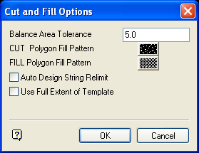
Cut and Fill Options panel
Balance Area Tolerance
Enter the tolerance level. Cuts and fills are assumed to be balanced if they are in the specified balance tolerance of each other.
CUT Polygon Fill Pattern
Select a pattern for the cut polygons.
FILL Polygon Fill Pattern
Select a pattern for the fill polygons.
Auto Design String Limit
Select this check box to use relimiting. When checked, any extents of the design string past the surface string intersections are removed. This is useful when creating the design surface later.
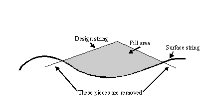
Figure 2 : No Relimiting
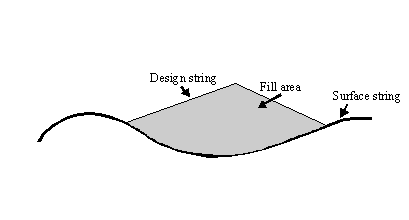
Figure 3 : Relimiting
Use Full Extent of Template
Select this check box to drop all vertical lines down or up from the template end points to form polygons. If unchecked, then the cut and fill polygons are only generated where the surface and design strings intersect.
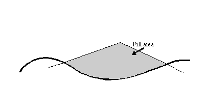
Figure 4 : Template Intersection Only
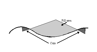
Figure 5 : Full Extent
The Cut and Fill options are stored in the <proj>envis.defaults file.
Delete Cut and Fill polygons
Allows the deletion of any generated cut and fill polygons, along with the design line.
The first four options allow the template string to be shifted about the Section window. After each positional shift, the cut and fill polygons are calculated and temporarily displayed, along with each polygon's area. If correct, then the design can be kept or rejected and tried again. Keeping the design causes the program to:
- Create actual cut and fill polygon objects. These objects are used by the cut and fill end area volume calculations. They can be deleted by using the Delete Cut and Fill polygons option.
- Create a new design string at the current template offset. This string can then be triangulated (from plan view) along with all other design strings, (selecting by feature), to form the new design surface.
- Update the template position by applying the current template offset to the template coordinates. This allows you to create a design surface with a common shape at a uniform level.

