Drill Hole Warning
Use the Drill Hole Warning option to highlight and report details on holes that exist in a nominated 3D distance of centrelines or triangulations. The drillholes can be contained in one or more databases.
Instructions
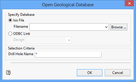
On the Underground menu, point to Analyse, and then click Drill Hole Warning to display the Open Geological Database panel.

Select one of the following options:
Isis File : Select this option to nominate an Isis database. The drop-down list displays all Isis database files found in your current working directory. Click Browse to select a file from another location.
ODBC Link : Select this option to nominate an ODBC link database. Select the design name from the drop-down list.
Selection Criteria
Enter the name of the desired drillholes. Wildcards (* multi-character and ? single character) can also be used.
Grade units
Select the applicable grade unit and the desired unit measurement (for example per metric tonne, per kilogram, per ounce, etc.) from the drop-down boxes. Drillhole naming is case sensitive, for example 'TQ1' is different than 'tq1'.
| Example | Description |
|---|---|
| L* | Select all drillholes that begin with 'L'. |
| L1? | Select all drillholes that begin with 'L' and contain '1' as the second character. |
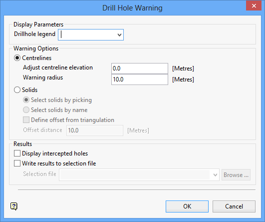
Click OK to display the Drill Hole Warning panel.

Drillhole legend
Select the drillhole colour legend that will be used to colour the drillholes. In the case of non-logged intervals, the colour specified for the Use Colour for non-logged intervals check box (on the Legend Editor interface) will be used. The available drop-down list contains all drillhole colour legends found in your Vulcan colour legends file (.scd).Enter appropriate cutoff value.
Centrelines
Select this option is you want to check for drillhole locations that fall in a nominated area of influence (around the centrelines). You will be prompted to select the centrelines after completing this panel.
The adjusted centreline elevation value refers to the area of influence around the centreline, that is, the number of units above the centreline, while the warning radius value refers to the radius that will be applied to the chosen centrelines. Any holes that intercept this radius will be flagged.
Solids
Select this option to check for drillhole locations that intercept nominated solid triangulations. Choose Select solids by picking to select triangulations directly from the screen. In order to do this, the desired triangulations must be loaded onto the screen prior to running the Drill Hole Warning option.
Alternatively, you can check the Select solids by name check box to select the triangulations by name. Choose Select solids by name to browse through your available data directories, that is, use triangulation files found outside of you current working directory.
Check the Define offset from triangulation check box to add an offset to a triangulation. The drillhole will be considered as intersecting the triangulation if it is in the specified offset value.
Display intercepted holes
Select this check box to display the holes that intercept the nominated triangulations or, if applicable, the area of influence around the centreline. The holes will be coloured according to the drillhole colour legend chosen at the top of the Drill Hole Warning panel.
Write results to selection file
Select this check box to output the results to a drillhole selection file (.sel). The drop-down list will contain all.sel files found in the current working directory. Click Browse to select a file from another location.
To create a new file, enter the file name and file extension.
Click OK.
If you have chosen to use centrelines, then the Multiple Selection box displays. From the displayed dialog box, nominate a selection method followed by the necessary objects.
If you have chosen to use solid triangulations, then you will be required to select the triangulations from the screen or, if you checked the Select solids by name check box, through using the standard Open panel.

