Centre Line
Use Centre Line to create centre lines for the underground development. Primitives can be applied to the centre lines using the Primitives option, or wall outlines can be created by using the Wall Outline option. The centre lines will be assigned the group name of CENTRE_LIN.
Click to view the Centre Line tutorial.
Instructions
On the Underground menu, point to Development, and then click Centre Line to display the Select Mode dialog box.
Select Create or Append from the Select Mode dialog box.
Design
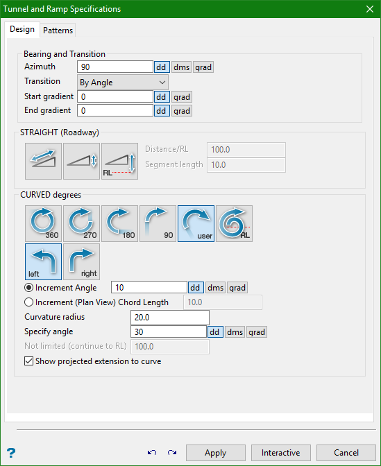
Azimuth
Enter the azimuth (as degrees). Once a line is created, the azimuth is automatically updated to follow the direction of the previous segment.
Start of gradient
The start gradient is used for the duration of the line. This is functionally equivalent to setting the start gradient and end gradient to the same value.
Constant gradient
Enter the azimuth (as degrees). Once a line is created, the azimuth is automatically updated to follow the direction of the previous segment.
End gradient
The gradient of the line is interpolated from the start gradient value to this end gradient value.
STRAIGHT (Roadway)
Select this option to create a straight ramp. You will need to specify the distance (the unit of measurement is set in the.dg1 file). The distance can be defined through one of three methods:
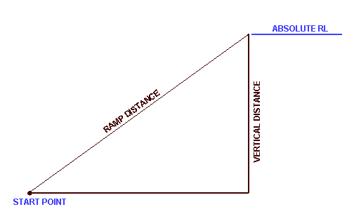
Figure 1 : Roadway Distance
|
|
Ramp - Distance defined along Roadway. This is the ramp distance, measured along the specified gradient, along the roadway. |
|
|
Vertical - Distance defined by Relative Elevation. The roadway will extend along the specified gradient until the vertical distance (elevation gain/loss) has been attained. |
|
|
RL - Distance defined to Absolute Elevation. The roadway will extend along the specified gradient until the absolute elevation (RL) has been attained. |


Note: A warning message appears if a roadway at the specified gradient will not reach this RL.
CURVED DEGREES
|
|
360° - Defines a full turn. |
|
|
270° - Defines a three quarter turn. |
|
|
180° - Defines a half turn. |
|
|
90° - Defines a quarter turn |
|
|
User - Defines a user specified turn. |
|
|
RL - Defines a turn limited by RL. |
|
|
Right - Defines a turn as a right turn. |
|
|
Left - Defines a turn as a left turn. |


Increment Angle
Select this option to specify an increment angle. The increment angle determines how many chords are required to make up the curve. The angle is entered in degrees. Instead of an increment angle you can specify an increment chord length (see next field).
Increment (Plan View) Chord Length
Select this option to specify the (Plan view) length of each chord making up the curve. This means that for a gradient of 1:10 and a chord length of 10m, there will be a 1m difference in elevation between each point on the curve.
Curvature radius
The default radius, which can be overwritten, is derived from the Underground Development preferences file (UGDEV.prefs). This file is created through using the Set Up option.
Specify angle
The angle of sweep (curve) may be defined as Full, Three quarter, Half, Quarter, a specified angle or as not limited.
Not limited (continue to RL)
The angle of sweep (curve) may be defined as Full, Three quarter, Half, Quarter, a specified angle or as not limited. In the latter case the angle continues to the RL.
Show projected extension to curve
Select this check box to show the projected straight line extension to the curve.
Undo/Redo
Undo or repeat the last action.
Apply
Apply the line and continue designing.
Interactive
Remain in the Centre Line Panel and use interactive edit commands without clicking out of the function. Once the interactive edit is made, select Apply and continue designing in the panel.
Cancel
Close the panel and return to the Create/Append prompt.
Patterns
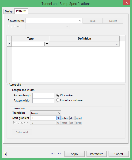
Pattern name
Select an existing pattern or define a new one.
Repetitions
Select whether to repeat the pattern a defined number of times or continue the patterne until reaching a specific level.
Type
Select a straight or curved pattern.
Definition
Click ![]() to display the Pattern Definitions panel.
to display the Pattern Definitions panel.
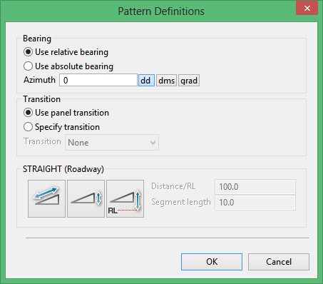
Use this panel to select the options for the defined pattern segment.
Select Use relative bearing to use the design tab azimuth plus your defined azimuth.
Select Use absolute bearing to use the azimuth as the bearing without taking into account the previous segment.
Select Use panel transition to use the design tab transition, or use Specify transition to define your own transition.
Autobuild
Use Autobuild to enter a length and width and direction as well as the Transition information that will be used for each segment. The grid is them populated with the information to build a spiral of that length and width.
This is not automatically saved and it overwrites information that exists in the grid.
Autobuild will always start with a straight segment, so the length should always be greater to or equal to the width.
Undo/Redo
Undo or repeat the last action.
Apply
Apply the line and continue designing.
Interactive
Remain in the Centre Line Panel and use interactive edit commands without clicking out of the function. Once the interactive edit is made, select Apply and continue designing in the panel.
Cancel
Close the panel and return to the Create/Append prompt.

