Wall Outline
Use Wall Outline to create a wall outline by specifying the width of the walls away from the centreline.
Instructions
On the Underground menu, point to Development, and then click Wall Outline to display the Wall Defaults panel.
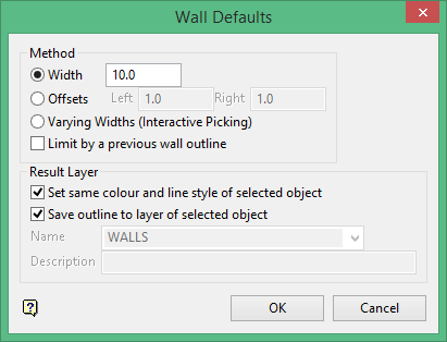
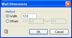
Method
Width
Select this option to produce a wall outline that is the same distance on both sides of the centreline. The default width, which can be overwritten, is derived from the Underground Development preferences file (UGDEV.prefs). This file is created through using the Set Up option.
A width of '10' will produce a wall outline that is 5 feet/metres from the left of the centreline and 5 feet/metres from the right of the centreline.
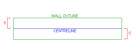
Figure 1 : Assigning a Fixed Width of '10'
Offsets
Select this option if you want to produce a wall outline that has a different width on each side of the centreline, for example 3 feet/metres to the left of the centreline, and 5 feet/metres to the right of the centreline.
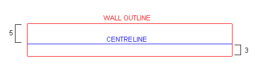
Figure 2 : Assigning Offsets of '5' and '3'
Varying Widths (Interactive Picking)
Select this option to produce a wall outline with varying widths
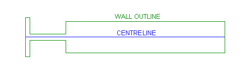
Figure 3 : Assigning Varying Widths
If this option is selected, then the Wall Dimensions panel displays once the Wall Defaults panel has been completed.
Limit by a previous wall outline
Select this check box to prevent the occurrence of self crossing wall polygons by limiting the proposed wall outline against an existing wall outline. If this check box is enabled, then a wall outline won't be created where one already exists. You will be required to select the wall outline to limit against upon completing this panel.
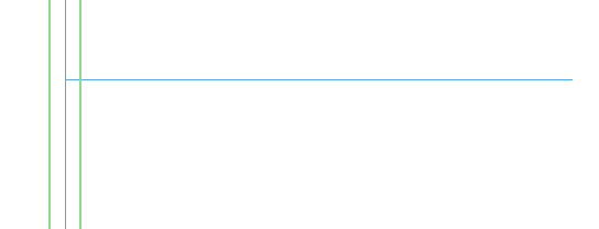
Figure 4 : The Original Wall Outline
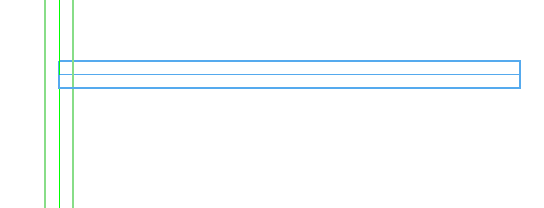
Figure 5 : Standard Wall Outlines
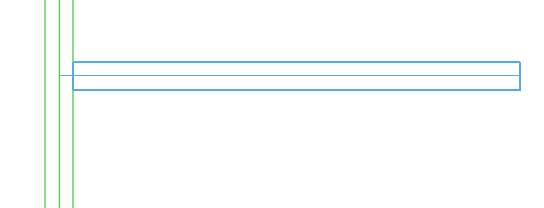
Figure 6 : Limiting by a Previous Wall Outline
Result Layer
Set same colour and line style of selected object
Select this option to assign the same colour and line style to the new wall outline as the centreline.
Save outline to layer of selected outline
Select this option to save the wall outline to the same layer as the centreline.
Name
Select the layer that will be used to store the wall outline (the default layer name is WALLS).
The drop-down list contains the names of all currently loaded layers. If you select an existing layer, then the resulting data will be appended to the nominated layer. If you enter the name of an existing layer that is not currently loaded, then you will need to confirm whether you want to load the layer or replace it, that is, overwrite its contents.
To store the wall outline in an existing layer that is not currently loaded, enter the layer name.
To create a new layer, enter the layer name. The layer name:
-
- may contain up to 40 characters.
- must begin with an alphanumeric character [0-9] or [a-z].
- cannot include spaces.
- can include hyphens [ - ], plus signs [ + ], underscores [ _ ], periods/dots [. ].
- can include the special characters of ÁÂÃÀÇÉÊÍÓÔÕÚÜÑ that are used in the Spanish and Portuguese languages.
Description
Enter a description to further describe the contents of this layer. The description can be up to 80 alphanumeric characters and may include spaces. If a description is not entered, then a default description will be used instead. If the chosen layer already has an assigned description, the description displays when the layer is selected. Existing layer descriptions can be overwritten
Click OK.
The panels and/or prompts displayed depend upon the method chosen through the Wall Defaults panel.
- Assigning a fixed width or offset
- Limiting by a previous wall outline
- Assigning varying widths
Assigning a fixed width or offset
Once the Wall Defaults panel has been completed, the Multiple Selection box displays. This to select the centrelines by category. Cancel when finished selecting centrelines.
You will then be asked whether or not to produce the outlines. Restart cancels the selected centrelines and returns to the Multiple Selection box. Outline creates the wall outlines based on the specified distance values.
The resulting wall outline is produced as a closed polygon. The polygon is assigned the group name WALL_OUTLI. The new wall outline will inherit the name of the chosen centreline, for example if the centreline's object name is LINE$1 , then the object name of the new wall outline will be LINE$1 as well.
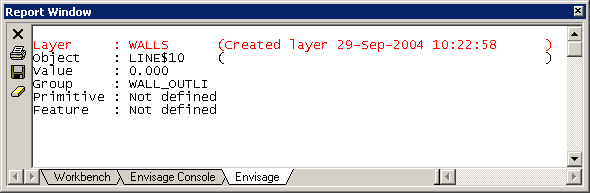
Figure 7 : Wall Outline Information (as viewed through the Report Window)
You are then prompted to select another centreline. Right-click to cancel out of the Wall Outline option.
Limiting by a previous wall outline
Once the Wall Defaults panel has been completed, the Multiple Selection box displays. This to select the limiting object by category. Cancel when finished selecting the limiting objects.
Select the appropriate centreline.
Specify whether or not to produce the outlines. Restart cancels the selected centrelines and returns to the Multiple Selection box. Outline creates the wall outlines based on the specified distance values.
The resulting wall outline is produced as a closed polygon. The polygon is assigned the group name 'WALL_OUTLI'. The new wall outline will inherit the name of the chosen centreline, for example if the centreline's object name is 'LINE$1', then the object name of the new wall outline will be 'LINE$1' as well.
Figure 8 : Wall Outline Information (as viewed through the Report Window)
Assigning varying widths
Select the appropriate centreline. You will then be prompted to select a line segment in the chosen centreline.
Once selected, the Wall Dimensions panel displays.
Method
Width
Select this option to produce a wall outline that is the same distance on both sides of the centreline. The default width, which can be overwritten, is derived from the Underground Development preferences file (UGDEV.prefs).
For example: A width of '10' will produce a wall outline that is 5 feet/metres from the left of the centreline and 5 feet/metres from the right of the centreline.
Offsets
Select this option to produce a wall outline that has a different width on each side of the centreline, for example 3 feet/metres to the left of the centreline, and 5 feet/metres to the right of the centreline.
Click OK.
You will then be prompted select an line segment in the chosen centreline. The Wall Dimensions panel displays each time a line segment is indicated. Cancel when you have finished assigning a width or offset value.
If you try to exit the option without assigning a wall outline to all of the line segments in the chosen centreline, then the Unassigned Segments panel displays.
Leave unassigned as is
Select this option if you don't want to assign a wall outline to any of the remaining unselected line segments.
Assign width
Select this option to assign a specific wall outline width to all of the remaining unselected line segments.
Example: A width of '80' will result in a wall outline that is 40 feet/metres from the left of the centreline and 40 feet/metres from the right of the centreline for all of the remaining line segments.
Click OK.
The resulting wall outline is produced as a closed polygon. The polygon is assigned the group name 'WALL_OUTLI'.. The new wall outline will inherit the name of the chosen centreline, for example if the centreline's object name is LINE$1 , then the object name of the new wall outline will be 'LINE$1' as well.
Figure 9 : Wall Outline Information (as viewed through the Report Window)
You are then prompted to select another centreline. Right-click to cancel out of the Wall Outline option.

