Cross Cuts
Use this option to quickly create access drives, safety bays, muck bays, and turnarounds along declines and other development openings. Strings are generated from a centreline or a wall outline.
Instructions
On the Underground menu, point to Development, and then click Cross Cuts.
Follow these steps:
-
Prior to using this option, create a centreline (polyline) that will be used to anchor all the cross cuts, and save it as a layer.
Note: You can create cross cuts originating from existing cross cuts.
-
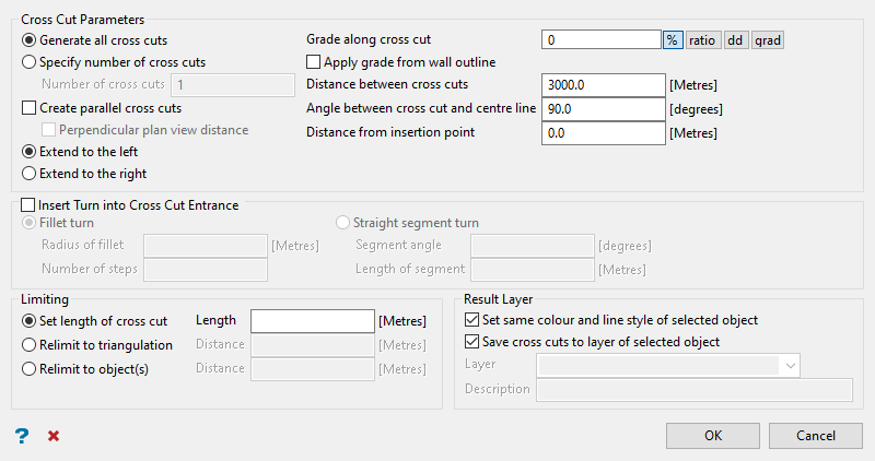
Set the number of cross cuts.
Select Generate all cross cuts if you want to create cross cuts along the entire length of the selected centreline. The cross cuts will begin at the location that you click on the string and continue until the end of the string.
Select Specify number of cross cuts to only create the number of cross cuts you enter into the box labelled Number of cross cuts. The cross cuts will begin at the location you click on the centreline and continue until all the cross cuts have been created. If the end of the centreline is reached before all the cross cuts have been created, you will be given the option to extend the length of the centreline or end the process.
Tip: Enter a large number for the cross cuts to ensure they are created along the entire length of the line. It is easier to delete extra cross cuts than to create additional cross cuts.
-
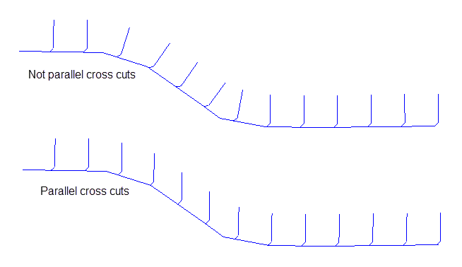
Select Create parallel cross cuts if you want to create cross cuts that are parallel to one another regardless of any changes to the centreline. The size of the angle between the first cross cut and the centreline is the value entered in the Angle Between Cross cut and centreline field. The remaining cross cuts are parallel to the first cross cut.
Check the Perpendicular plan view distance check box if you want the distance between each cross cut to be a measured as if looking from plan view. If this check box is not checked, then the distance between each cross cut will be the distance measured along the centreline.
TipIt is good practice to leave the Create parallel cross cuts and Perpendicular plan view distance boxes checked as this will line up the cross cuts correctly even if the main drive is at an angle.
-
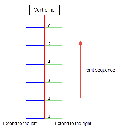
Select either Extend to the left or Extend to the right to determine which side of the centreline the cross cuts will be created. The orientation of the centreline will depend on the point sequence direction.
-
Enter the grade (slope) value in the box labelled Grade along cross cut. The grade can be entered as a percentage, ratio, decimal degrees, or gradians.
-
Select Apply grade from wall outline if you want the grade of a cross cut to be applied from where the centreline of the crosscut intersects the wall outline of the drift. If this check box is not selected, then the grade will be applied from where the centreline intersects the cross cut.
Note: Aim to keep at least a 1% or 2% grade on the cross cuts for drainage.
-
Enter the Distance between each cross cut in the space provided.
-
Enter the Angle between the cross cut and the centreline. Zero (0 ° ) is in the direction of the centreline, 90° is perpendicular to the centreline and 180° is in the opposite direction to the centreline.
Note: Some equipment cannot make a 90° turn. Therefore, 60° is often used for Angle between cross cut and centreline.
-
Set the Distance from insertion point. This determines the distance along the centreline from the point you click to the point where the cross cuts will begin.
-
Select Insert a turn into the entrance if you want to design a graduated turn at the beginning of the cross cut. You will need to specify the turn type.
-
Fillet turn - You will need to specify the turning radius and the number of steps (sections) to approximate the arc.
-
Straight segment turn - You will need to specify the angle between the segment and centreline, as well as the true length of the segment.
-
-
Set the length of the cross cuts by selecting one of the Limiting options.
-
Set length of cross cut - Select this option if you want a set length.
-
Relimit to a triangulation - Select this option if you want to limit the cross cuts by a distance from a nominated triangulation. The distance is referenced from the far side of the triangulation.
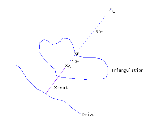
Distance =
10m, X-cut ends at ADistance =
0m, X-cut extends all the way through the triangulation (B)Distance =
-50m, X-cut extends to 50m beyond far side (C) -
Relimit to object(s) - Select this option if you want to limit the cross cuts by a distance from a nominated polyline.
-
-
Click OK.
You will then be prompted to select the centreline from which to extend the cross cuts, then the start point. If you have selected the Relimit to triangulation option and more than one triangulation is loaded, you will be prompted to select the correct triangulation.
After the cross cuts have been created, you will be returned to the Cross Cut Development panel.
-
Click Cancel when finished creating cross cuts.

