Create Hole 
Use the Create Hole option to create individual offset or radial blastholes. Any new holes created by this option will be added to the working layout.
The format of the blasthole names is <working layout><sequence number>. The holes are placed in a temporary layer called DIG$UGB with each hole being considered an object and its name placed in both the object name and object description fields.
The entry in the object description field is stored in the HOLEID field of the HEADER table and is used to access the holes. The entry in the object name field, which can be changed through the Change Sequence option, is used for reporting and plotting purposes. The holes are assigned the feature UGLAYOUT , as well as a group name equal to the working layout.
This option can also be accessed by selecting the Create Hole button ![]() from the UG Ring Design toolbar.
from the UG Ring Design toolbar.
Note: The Layout Pattern or Fill Pattern option can be used to create multiple blastholes. The working layout needs to be set prior to using this option. Use the Navigate Section option to set the working layout.
Instructions
On the Underground menu, point to Ring Design, and then click Create Hole to display the Digitise Blasthole panel.
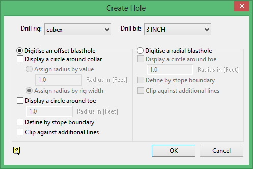
Drill rig
Enter, or select from the drop-down list, a drill rig.
Dill bit
Enter, or select from the drop-down list, a hole diameter. The diameter of the hole will be used in the ring design reporting and in calculating the weight of the explosives used in explosive columns for this hole.
Digitise an offset blasthole
Select this option to create offset blastholes. Offset blastholes are created by explicitly indicating a collar and toe location.
Display a circle around collar
Select this check box to display a circle around the collar location. This circle can be used to ensure that a new blasthole's collar point is a set distance from any surrounding blasthole collars.
Display a circle around toe
Select this check box to display a circle around the toe location. This circle can be used to set the toe spacing between any surrounding blastholes. You will need to specify the radius of the circle. The radius can either be defined by a specified value ( Assign radius by value ) or the width of the chosen drill rig can be used ( Assign radius by rig width ).
Define by stope boundary
Select this check box to extend the blasthole through to a stope polygon. The blasthole's length will be extended to the last intersection between the stope and the hole, however, this is only if the toe spacing allows it.
Clip holes against additional lines
Select this check box to allow a blasthole to be optionally clipped against lines in addition to the stope boundary. This option is useful when constructing interlocking patterns of holes. By digitising a line where two or more patterns meet, each blasthole can be constructed without interfering with other areas of the stope.
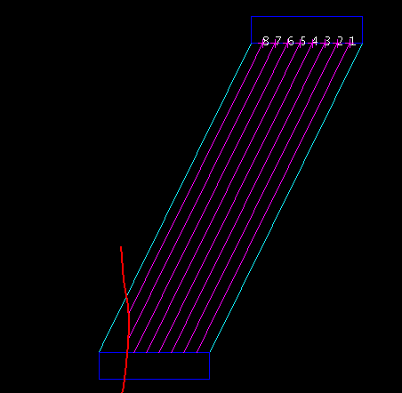
Figure 1 : Clipping Holes
Digitise a radial blasthole
Select this option to create radial blastholes. Radial blastholes are created by indicating the hole's toe point and then determining the collar location as the intersection of a line between a fixed pivot point and the indicated toe location, and a drive (or sill) polygon.
Display a circle around toe
Select this check box to display a circle around the toe location. This circle can be used to set the toe spacing between any surrounding blastholes. You will need to specify the radius of the circle.
Define by stope boundary
Select this check box to extend the blasthole through to a stope polygon. The blasthole's length will be extended to the last intersection between the stope and the hole, however, this is only if the toe spacing allows it.
Clip holes against additional lines
Select this check box to allow a blasthole to be optionally clipped against lines in addition to the stope boundary. This option is useful when constructing interlocking patterns of holes. By digitising a line where two or more patterns meet, each blasthole can be constructed without interfering with other areas of the stope.
Click OK.
If you chose to digitise a radial blasthole, then you will need to select the drive polygon and pivot point. You will then need to indicate the toe location of the new blasthole.
If you chose to create an offset blasthole, then you will need to indicate a collar followed by the toe location. Whenever a blasthole toe or collar point is being picked, their location can be indicated repeatedly until you are satisfied with the selected point. Cancel to accept the point.
After the hole has been digitised, you will be asked to confirm its creation. Upon confirmation, the new blasthole is added to the working layout and saved to the database. You can then select another toe or collar point. Cancel when you have finished creating blastholes.
You will then be prompted to pick the stope polygon (if defining holes by stope boundary), clipping lines (if appropriate) and the reference hole. If you are constructing radial blastholes, then you will also be prompted for the drive polygon and a pivot point.
The new hole is then created. Confirmation of the new hole is required before it will be saved.
Retain and layout next
Associates the new blasthole with the working layout and saves it into the database. The new blasthole will be used as the new reference hole and the next blasthole in the sequence will be created.
Reverse current hole
Changes the direction of mislaid blastholes.
Retain hole
Associates the new blasthole with the working layout and saves it into the database. You will then be prompted to select another reference hole.
Reject hole
Rejects the new blasthole and prompts to pick a new reference hole.

