Create Ring Profiles
Once you have created a ring layer, you are ready to set up ring profiles. The Create Ring Profile option takes a 3D model of a section of material to be mined, and separates it into slices or cuts, which can be used for ring design, as shown below.
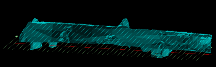
Figure 1 : Sectioned Triangulation
Tutorials
View the Underground Ring Design tutorials
Instructions
Follow these instructions to slice a triangulation of a block of mineable material for use in ring design.
- From the Explorer Window in Design Databases, load a section layer to use as a reference when slicing the material to be mined.
- From Triangulations, load a triangulation representing the material to be mined.
- On the Underground menu, point to Ring Design, and then click Create Ring Profiles. The 3D Section Profiles panel displays.
- In the 3D Section Profile panel, for Section layer, type the name of a new layer, or select a loaded layer from the drop-down list.
- If you are slicing the block as part of designing a ring, then in Sections, select Irregular sections, and follow steps a and b below. For more information on using Equidistant sections, see Sections .
- Select Use cross section lines, and Get the dip angle from the object value.
- Select Include the object name when naming the sections, and to follow naming conventions, select Apply the name as prefix.
- For Triangulations, choose a method of selecting a triangulation. For more information, see Triangulations .
- Click OK.
- Next, select a line to act as a reference when slicing the mining material. For more information, see Line selection .
- If required, select a triangulation. For more information, see Triangulations .
- A model of sliced mining material should display, which can be used for ring design.
The 3D Section Profile panel
3D Section Profiles panel
Section Layer
Select the layer that will be used to store the sections.
The drop-down list contains the names of all layers found within the currently open design database. If you select an existing layer, then the resulting data will be appended to the nominated layer. If you enter the name of an existing layer that is not currently loaded, then you will need to confirm whether you want to load the layer or replace it, that is, overwrite its contents.
To create a new layer, enter the layer name. The layer name:
- may contain up to 40 characters.
- must begin with an alphanumeric character [0-9] or [a-z].
- cannot include spaces.
- can include hyphens [ - ], plus signs [ + ], underscores [ _ ], periods/dots [. ].
- can include the special characters of ÁÂÃÀÇÉÊÍÓÔÕÚÜÑ that are used in the Spanish and Portuguese languages.
Description
Type a description for the section layer in this field. The description can be up to 80 alphanumeric characters and may include spaces. If a description is not entered, then a default description will be used instead. If the chosen layer already has an assigned description, the description displays when the layer is selected. Existing layer descriptions can be overwritten.
Sections
You can create equidistant or irregular sections.
Equidistant sections
Select this option to create sections that are at a specified distance apart. You will need to specify a value for Section spacing. There is a choice of three section calculation methods:
Calculate all sections
Select this option to use the distance between sections to calculate all sections.
This calculates all sections possible through a triangulation. The location of the first section (from which the remainder are derived) is defined by the plane specified in the Section Definition panel.
Calculate one section
This calculates only one section, which is defined by the plane specified in the Section Definition panel.
Calculate a range of sections
Select this option to use the distance between sections to calculate a range of sections. Define the range of the sections in the Number of back sections and Number of front sections fields.
Regardless of the method chosen, the Section Definition panel will be displayed once the 3D Section Profiles panel has been completed.
Irregular sections
Select this option to create a section parallel or perpendicular to an existing line. Specify, if applicable, the dip of the section plane.
Use cross section lines (profile parallel to line)
Select this option to create sections along lines defined by the user.
Use guide centre line (profiles normal to line)
Select this option to create sections perpendicular to line segments, at points on the line.
Triangulations
The triangulation name (minus the path and file extension) will be used as the name, group and description of the created sections.
Select triangulations by picking
Select this option to pick the triangulations from the screen. Check the Pass triangulation's colour onto sections check box to pass the solid's colour onto the sections. If this check box is not selected, then the default colour will be used instead. The default colour is specified through the Status toolbar.
Select triangulations by name
Select this option to select the triangulations using the standard Open panel. Once the section (either irregular or equidistant) has been established, the Open panel displays.
The left half of the panel contains all of the triangulations found in your current working directory. Use the Look in field drop-down list to change to a different directory.
Select the triangulation(s) you want to section (the standard windows selection methods apply). Use the ![]() button to move the selected triangles to the selection section of the panel. Select OK to select the triangulations.
button to move the selected triangles to the selection section of the panel. Select OK to select the triangulations.
You can save the selection by checking the Save Selection check box if you think you will want to reselect the same triangulations. To use a selection file to select the triangles, change the files of type to selection files ( *.sel) and select your selection file. Refer to the to Open option for more information on the Open panel.
Select loaded triangulations
Select this option to section all of the triangulations that are currently loaded onscreen. Check the Pass triangulation's colour onto sections check box if you want to pass the solid's colour onto the sections. If this check box is not checked, then the default colour will be used instead. The default colour is specified through the Status toolbar.
Click OK.
Line Selection
The method of line selection depends on whether you have selected Equidistant Sections or Irregular Sections .
Equidistant Sections
If you chose to create equidistant sections, then the Section Definition panel displays, providing options for selecting a section.
Section Definition panel
Dip
The dip is the angle of the section from horizontal. Valid dip angles are between -90° and 90°.
Select section by line
Select this option to define the plane by selecting an existing line and specifying the dip.
Only design strings may be picked and it is not possible to pick a line in an underlay. The direction of the view, and therefore the direction of the stepping, depends on the digitised sequence of the line. The digitised sequence of the line can be reversed using the Design > Object Edit > Reverse option.
Select by points
Select this option to define the plane by digitising two points and specifying the dip.
To locate a point precisely, use the Snap to Objects or Snap to Points modes (on the Digitise toolbar). Points may be snapped onto underlays, such as block model slices or triangulations. If you use Indicate mode to select the points, then the points have the current default Z value.
Select by grid coordinate
Select this option to define the plane by using a specific grid coordinate. The grid co-ordinates can contain up to three decimal places. To achieve the best results for the following three methods, we recommend using the Zoom Data Extents icon (on the Graphics toolbar) in order to view all of the graphics.
- By Easting - Select this option to enter a specific Easting value (X value).
- By Northing - Select this option to enter a specific Northing value (Y value).
- By RL - Select this option to enter a specific RL value (Z value).
Select by 3 points
Select this option to define the plane by digitising 3 points. To locate a point precisely, use the Snap to Objects or Snap to Points modes (on the Digitise toolbar). Points may be snapped onto underlays, such as block model slices or triangulations.
Using this option will allow you to explicitly define the location and orientation of a plane by indicating 3 points. The first two points define the bearing of the plane, and the third point defines the dip of the plane.
Click OK.
Irregular Sections
If you chose to create irregular sections, then you will need to select the line that will be used to create the necessary sections.
After selecting one or more lines, an error message may appear. Click OK in the error message.
The surface(s) is then sectioned. If you chose to use the Select solids by picking or Select solids by name options, then you will be required to select the necessary triangulations before the sections are created.

