Fill Hole Pattern 
Use the Fill Hole Pattern option to create multiple blastholes (automatically) for a layout according to a set of layout definition parameters. The new holes will be positioned between two existing holes. These two existing holes are referred to as reference or constraining holes. They ensure that the new holes are confined and parallel to the reference holes.
The Fill Hole Pattern option is similar to the Layout Hole Pattern option, however, the latter does not guarantee that the last created hole is parallel to a nominated structure, such as footwall or floor.
This option can also be accessed by selecting the Fill Pattern button from the UG Ring Design toolbar.
Note: A blast design specification file (Blasting.spc) must exist prior to using this option.
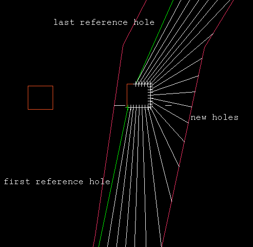
Figure 1 : Multiple Holes Between Existing Holes
The format of the blasthole names is <working layout><sequence number>. The holes are placed in a temporary layer called DIG$UGB with each hole being considered an object and its name placed in both the object name and object description fields.
The entry in the object description field is stored in the HOLEID field of the HEADER table and is used to access the holes. The entry in the object name field, which can be changed through the Change Sequence option, is used for reporting and plotting purposes. The holes are assigned the feature UGLAYOUT, as well as a group name equal to the working layout.
Instructions
On the Underground menu, point to Ring Design, and then click Fill Hole Pattern to display the Fill Hole Pattern panel.
If you have not already loaded a blast database, you will be prompted to do so. For instructions on how to do this, see Open Blast Database .
If you have not already set a current ring, you will be prompted to do so. For instructions on how to do this, see Display Rings .
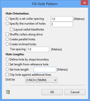
Hole Orientation
Specify a set collar spacing
Select this option to create blastholes separated at the collar points by a specified distance measured around the drive polygon (the distance can be changed at a later stage). Specifying a set collar spacing is useful when collar spacing is important. However, specifying a number of holes (see next field) is more flexible.
Specify the number of holes
Select this option to specify the number of holes to be created. Specifying a number of holes is the best option with which to start your design. The number can be changed at a later stage.
Layout radial blastholes
This option only allows the pattern to be defined by entering a number of holes, not by collar spacing. Radial holes and parallel holes are mutually exclusive. Radial holes require that an origin point is nominated from which holes will be projected to the stope boundary. The drive and stope polygons must also be identified.
Shuffle collar along drive
Select this check box to ensure that hole collars remain on the drive polygon. When creating blastholes by a set collar spacing, the collar will be shuffled the specified distance along the drive polygon. If you are creating a set number of blastholes, the collar location will be calculated by dividing the perimeter of the drive outline between the first and last reference hole by the number of holes specified.
Create parallel holes

