Create/Edit Blast Specification File
Use the Create/Edit Specification File option to create or edit the specification file that is to be used in the Ring Design and Explosive Loading modules. Unlike Version 5.0, which used the older <proj>.ug_spec specification file, this module uses the new Blast Design specification file (Blasting.spc).
| <proj>.ug_spec file | Blasting.spc file | |
|---|---|---|
| Creation | Needs to be created through the use of a text editor. | Automatically created upon completing the UG Specification File panel. |
| Contents | Contains all drill bit and explosives library specifications. |
Contains all blasting specifications, such as:
|
| Storage location | Located in the current working directory. | Located in the directory pointed to by the $ENVIS_RESO environment variable ($VULCAN/etc/resources by default). |
Note: If the older.ug_spec file exists in your current working directory, then the contents of this file will be used to 'populate' the UG Specification File panel. Upon completing this panel, the older Blast Design specification file, which will be archived and renamed to <proj>.ug_spec-old, is replaced with the new Blasting.spc file.
If the Blasting.spc file does not exist in either the work area or Resources area, filling out this panel and clicking OK will generate the specification file in the user's Resources file. If the Blasting.spc exists in the user's Resources area, clicking OK here will re-save to the Resources area. If the Blasting.spc exists in the users work area, the file is read from that location and re-saves to that location. This allows users whose Resources area is public on a network to copy the Blasting.spc from the Resource area into their work area and modify the specification file without changing the file for other users.
Instructions
On the Underground menu, point to Ring Design, and then click Create/Edit Blast Specification to display the Create/Edit Blast Specification panel.
The interface consists of the following tabbed panels:
- Drill Bits
- Explosives
- Primers
- Cappings
- Toe Spacing
- Loading
- Drill Rigs
- Layouts
- Plotting
Drill Bits
Use the Drill Bits tab to create and define the contents of the drill bit library.
Units for drill bit diameter:
Specify the units for the drill bit diameter, that is, millimetres or inches.
Drill Bit Library:
Enter the details for the items in the drill bit library, that is, drill bit name and drill bit diameter.
Default Bit
Select the drill bit that will be used as the default.
Explosives
Use the Explosives tab to create and define the contents of the explosives library.
Explosives Library
Name
Enter the name for the explosive agent (spaces cannot be entered).
Type
Specify the explosive type, that is, 'BULK', 'STICK', 'PACKAGED', 'DECKING'.
Cost
Specify the dollar amount (per unit) for use in the calculation of blast cost.
Density
Enter the density (in g/cc) that will be used to calculate the weight of agent per hole.
Example: Lbs/ft = 0.34 x dia(inches) x density(g/cc)
Colour
Select the line colour for the explosive column. The colour is selected from the current colour table.
Line type
Select the line type for the explosive column. The line type is selected from a list of line types that is delivered with the system.
Tip: We recommend that you use a wider/bolder line type than that used by the blasthole line.
Decoupled
Select this check box to specify an alternate diameter for use with a decoupled charge. The calculations for powder weight over these lengths will use the specified diameter value instead of the drill bit diameter. If this check box is not enabled, then the drill bit diameter will be used by default.
Default explosive
Specify the explosive agent that will be used as the default.
Loading interval
Specify the default loading interval.
Primers
Use the Primers tab to create and define the contents of the primers library. The Blast Design specification file will support up to 1,000 different primer types.
Primer Library
Type
Specify the type of detonator to be used on the explosive column.
Cost
Specify the dollar amount (per unit) for use in the calculation of blast cost.
Density
Enter the density (in g/cc) that will be used to calculate the weight of agent per hole.
Example: Lbs/ft = 0.34 x dia(inches) x density(g/cc)
Symbol On/Off
Select this check box to associate a symbol with the corresponding capping type. If this check box is checked, then you will need to select the symbol that displays. You have the choice of using a circle, rectangle or triangle.
Default primer type
Specify the type of detonator that will be used as the default.
Primer Text Attributes
Font name
Select the font to be used when displaying the capping information. Only transformable (vector) fonts can be selected from the drop-down list,.
Text width in plotter units
Enter the height (in plotter units) for the text.
Map Scale for this size
Enter the scale (as a ratio) used by the text height.
Example: If you have a text width of 10 cm, and the map scale is 1:1250, then the text will appear on the screen the same size as an object that is 125 units long.
Capping
Use the Capping tab to create and define the contents of the cappings library. The Blast Design specification file will support up to 1,000 different capping types.
Capping Library
Type
Specify the type of detonator to be used on the explosive column.
Delay
This column allows you to specify the sequence number for the explosive columns in the blast. Select the ![]() button to display the Capping Delays panel.
button to display the Capping Delays panel.
Symbol On/Off
Select this check box to associate a symbol with the corresponding capping type. If this check box is checked, then you will need to select the symbol that displays. You have the choice of using a circle, rectangle or triangle.
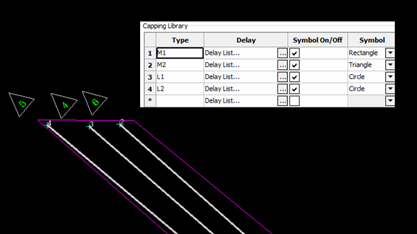
Figure 1 : Symbols Displayed
Default cap type
Specify the type of detonator that will be used as the default.
Capping Text Attributes
Font
Select the font to be used when displaying the capping information. Only transformable (vector) fonts can be selected from the drop-down list,.
Text width in plotter units
Enter the height (in plotter units) for the text.
Map Scale for this size
Enter the scale (as a ratio) used by the text height.
Example: If you have a text width of 10 cm, and the map scale is 1:1250, then the text will appear on the screen the same size as an object that is 125 units long.
Toe Spacing
Use the Toe Spacing tab to nominate the method that will be used to calculate toe spacing.
Method 1
The shortest distance between the two holes, starting at either the toe point, measured perpendicular to the reference hole.
Method 2
The shortest distance between the two holes, starting at either toe point, measured perpendicular to the new hole.
Method 3
The shortest distance between the two holes, starting at either toe point, measured perpendicular to the average direction of the two holes.
Method 4
The direct distance between the toe point of the reference hole and the toe point of the new hole.
Loading
Use the Loading tab to set the default explosive loading parameters for the Underground Blast Design module.
Explosive Loading Defaults
Split hole in sample intervals
Select this check box to produce downhole intervals for assay sampling. You will need to specify the sample interval. When a new hole is created or modified, the blasthole will have sample intervals inserted according to the specified length.
Minimum loading length
Enter the minimum length of an explosive column (the default value is '10.0'). This value is used by the Load Ring option as part of the rules to optimise automatically a ring design.
Desired stemming length
Enter the stemming length value preferred for the stemming of a hole. This value is used by the Load Ring option as part of the rules to optimise automatically a ring design. If the minimum loading length, and the desired stemming length are greater than the design hole length, then the stemming length will be shrunk to fit the blasthole. This means that the minimum loading length will precede the desired stemming length in the automatic load optimisation.
Minimum column spacing
Enter the minimum distance between two explosive columns. This value, which can contain up to 3 decimal places, is used by the Load Ring option as part of the rules to optimise a ring design. If two columns are too close together, then one of the columns is adjusted. The column can also be removed, this is temporary until you accept the load optimisation.
Blast envelope radius
Enter the radius of the blast envelope.
Drill Rigs
Use the Drill Rigs tag to create and define the contents of the drill rig library.
Drill Rig Library
Type
Enter the drill rig name.
Rig Design
Select the ![]() button to display the Drill Rig Description panel.
button to display the Drill Rig Description panel.
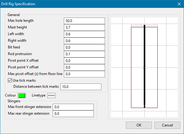
This panel allows you to specify the dimension for the rig, such as:
- The maximum hole length.
- The mast height.
- The width (left and right).
- The bit feed.
- The rod protrusion.
- The pivot point offset (X and Y).
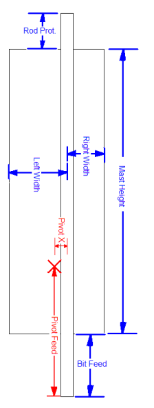
Figure 2 : Rig Dimensions
Click OK to return to the UG Blast Specification panel.
Default drill rig
Specify the default drill rig.
Layouts
Layouts define a basic drilling setup that can be used on the ring sections generated in the Automatic Ring Design utility. Any number of layouts can be added, with a default layout name defined.
Ring Layout Information panel
This allows you to define how the layout will work.
It defines the drilling layout style, such as radial, inclined, or parallel. It also defines the drilling direction such as up, down, left, or right.
The tool tries to determine the drift edges by finding the corner points closest to the drift extent. Drift segments are extracted in a CCW fashion.
Down - bottom of the drift, oriented L ![]() R
R
Right - Right edge of the drift, ordered Bot ![]() Top
Top
Up - Top edge of the drift, ordered R ![]() L
L
Left - Left edge of the drift, ordered Top ![]() Bot
Bot
Starting hole inclination (Parallel/Inclined only)
Defines the inclination of the first hole which subsequent holes are created from.
Pivot horizontal offset (radial only)
Defines the horizontal offset from the reference line to the radial pivot point.
Pivot vertical offset (radial only)
Defines the vertical offset from the reference line to the radial pivot point.
Start collar offset
Defines the offset from the edge of the drift to collar the first drillhole.
End collar offset
Defines the offset from the end of the drift face that stops creation of drillholes.
Drilling down, parallel drilling, start offset = 0.5, end offset = 1
The polyline from the bottom of the drift will be extracted. Collars will start at a 0.5 offset from the left and be created until the last hole is >1 from the right at a given collar spacing.
Drilling up, parallel drilling, start offset = 0.5, end offset = 1
Same as the example above, but start means the right edge and end = left edge.
Collar spacing (Parallel/Inclined)
Defines the spacing between the collar points
Toe spacing (Inclined/Radial)
Defined the spacing at the toe points, using the Toe Spacing measurement methodology defined in the specification file.
Hole Length
Base hole length prior to relimit options
Clip to stope
Clips drillholes to the stope, extending to the farthest intersection with the stope boundary.
Clip to boundary lines
Clips the drillholes to the extra boundary polygons. Either to stope or first intersection, whichever is shorter.
Plotting
Use the Plotting tab to assign a default drafting sheet for the Ring Design and Explosive Loading modules.
Plotting preferences
UGB plot template
Select the default drafting sheet for the Ring Design and Explosive Loading modules. The drop-down list displays the names of all drafting sheet found in your drafting database ( drafting.dgd.isis). Check the Always use default template check box if you want the chosen drafting sheet to be treated as the default. If this check box is checked, then the Pick Plot Template panel won't be displayed and the drafting sheet chosen through this tab will be automatically selected.
Click OK.
The defaults are then saved to the Blasting.spc file.

