General Reserves
Use General Reserves to perform interactive, ad-hoc reserve calculations on a selected triangulation.
All volumes that are to be evaluated are based on triangulations. If a stope is to be evaluated, then it should be divided into blocks that will be the mining blocks. If a number of mining levels exist, the solid model can be sliced by levels and the section through it can be evaluated. Evaluations can also be carried out by rings (see Ring Reserves option).
Instructions
On the Underground menu, point to Stope Design, and then click General Reserves to display the Reserve Calculation panel.
The directory path and filename of the currently open block model will be displayed at the top of the panel. The block model name will consist of the project code (<proj>), if specified, the block model file identifier (<bfi>), followed by the block model file extension (.bmf).
Grade variable
Up to 6 grade variables may be used in the calculation. The variables can be entered manually or selected from the drop-down list.
Use zone breakdown
Select this check box to use a zone variable, for example the geology variable.
Density
The density can either be a variable in a density field in the block model or a constant value. The variable can be entered manually, or selected form the drop-down list.
Save report to file
Check the Spawn reserves calculation in window check box if you want to run the reserves calculation in another window, thus freeing the current window for further Vulcan work.
Click OK.
The following panel is then displayed.
Use cut-off grades
Select this check box to use cut off grades. If checked, then you will need to enter the number of cuts and the cut off values (up to 13). The reserves report will include only those cutoffs for which values have been supplied, for example if you specified 13 cuts, but supplied only values for the first 5, then only the first 5 cuts will be reported.
Click OK.
The following panel is then displayed.
Either all blocks or specific blocks can be selected. If you select Select specific blocks by, then you must enter one or more of the following selection criteria:
Variable
Select this check box to restrict the blocks by a block model variable. You will need to specify the variable, as well as a particular value.
For example, to restrict blocks to those where Material equals Ore, select 'Material' as the variable (from the drop-down list) and enter 'Ore' as the value. However, if you require all blocks thatdo nothave this specified value, then enable the Reverse matching check box. The block model variable may be numeric (for example the grade variable 'Au') or character (for example 'Geology') variables.
Bounding box
Select this check box to restrict the blocks by a box. The bounding box is defined in Interactive or Coordinate mode. The required mode is selected from the Box Thickness panel, which is displayed once the Block Selection panel has been completed. You may also select the Use block centres check box and use it with this restriction.
Section thickness
Select this check box to restrict the blocks by a section plane. You will need to enter its associated thickness. The blocks that are within this thickness will be selected.
The section plane can be selected by line, points or grid coordinates. This information is entered through the Section Plane panel, which is displayed once the Block Selection panel has been completed. You may also select the Use block centres check box and use it with this restriction.
Condition
Select this check box to use a further constraint upon a numeric block model variable, for example Fe GT 10.0 (iron value greater than 10.0). The maximum size of the condition is 132 alphanumeric characters. A list of available operators/functions to use when defining this condition is provided in Appendix D.
Bounding Surfaces
Select this check box to restrict the blocks by bounding surfaces. Once the Block Selection panel has been completed, you will be required to select (from the screen) the top and bottom surface triangulations. Only blocks that lie within the overlapping sections, as viewed in plan view, of the surfaces are selected. You may also select the Use block centres check box and use it with this restriction. This check box will be disabled when the Cut and fill surfaces check box is in use.
Cut and fill surfaces
Select this check box to restrict the blocks to those that fall within two intersecting surfaces. This check box will be disabled when the Bounding surfaces check box is selected.
The required triangulation surfaces are specified through the Cut and Fill Surfaces Selection panel, which is displayed once the Block Selection panel has been completed.
Reverse matching
Select this check box to select outside the specified regions. See the description of the Variable field. This check box will be disabled when the Cut and fill surfaces check box is in use.
This check box is only available when using the Advanced Reserves Editor, or when limiting the block selection by a bounding box, triangulation or surfaces.
Use block centres
Select this check box to use the full cell evaluation method. If this check box is not selected, then the proportional cell evaluation method will be used instead.
Full cell evaluation : Include blocks if the block centroid is within the region. The entire block will be included.
Proportional cell evaluation : Include those block that touch the region, and evaluate reserves according to the proportion of the block's volume that lies within the region. Proportional cell evaluation calculates and reports the exact proportion of a block within a solid triangulation. When selecting blocks, all blocks that touch the region are selected.
Click OK.
The reserves are then calculated and displayed. If you are selecting blocks by section, then the Section Plane panel displays before the calculations are performed.
If the Use zone Breakdown option was selected, then both grades and zones are included in the report.
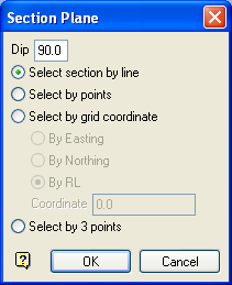
Section Plane panel
Dip
The dip is the angle of the section from horizontal. Valid dip angles are between -90° and 90°.
Select section by line
Select this option to define the plane by selecting an existing line and specifying the dip.
Only design strings may be picked and it is not possible to pick a line in an underlay. The direction of the view, and therefore the direction of the stepping, depends on the digitised sequence of the line. The digitised sequence of the line can be reversed using the Design > Object Edit > Reverse option.
Select by points
Select this option to define the plane by digitising two points and specifying the dip.
To locate a point precisely, use the Snap to Objects or Snap to Points modes (on the Digitise toolbar). Points may be snapped onto underlays, such as block model slices or triangulations. If you use Indicate mode to select the points, then the points have the current default Z value.
Select by grid coordinate
Select this option to define the plane by using a specific grid coordinate. The grid co-ordinates can contain up to three decimal places. To achieve the best results for the following three methods, we recommend using the Zoom Data Extents icon (on the Graphics toolbar) in order to view all of the graphics.
- By Easting - Select this option to enter a specific Easting value (X value).
- By Northing - Select this option to enter a specific Northing value (Y value).
- By RL - Select this option to enter a specific RL value (Z value).
Select by 3 points
Select this option to define the plane by digitising 3 points. To locate a point precisely, use the Snap to Objects or Snap to Points modes (on the Digitise toolbar). Points may be snapped onto underlays, such as block model slices or triangulations.
Using this option will allow you to explicitly define the location and orientation of a plane by indicating 3 points. The first two points define the bearing of the plane, and the third point defines the dip of the plane.
Click OK.

