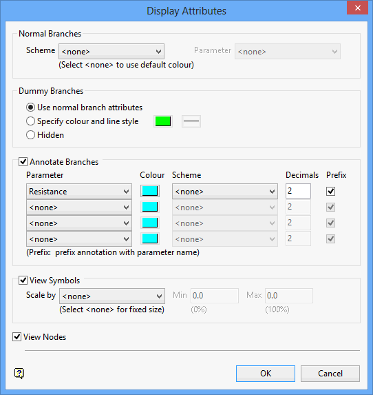
Display Attributes
Use Display Attributes to set the display attributes, such as branch annotations, line styles and colours, for the branches of the currently loaded network file. This option also to toggle the viewing of symbols and node numbers.
Instructions
On the Underground menu, point to Ventilation, and then click Display Attributes to display the Display Attributes panel.

Normal Branches
This section to specify the display attributes for normal branches. Normal branches can either be coloured by a nominated colour scheme/legend, or by using the default branch colour (specified through the Defaults option).
Refer to the Legend Editor option (under the Analyse > Legend Edit submenu) for information on how to create a colour scheme/legend.
Scheme
Select, from the drop-down list, the name of the contour colour scheme/legend that you want to apply to the normal branches contained in the loaded network file. Selecting <none> will result in the default branch colour being used.
Parameter
Select, from the drop-down list, the name of the parameter that represents the colour that you want to apply to the normal branches.
Note: If the chosen parameter is not found, then the default branch colour will be used instead.
Dummy Branches
This section to specify the display attributes for dummy branches.
Use normal branch attributes
Select this option to use the normal branch attributes when displaying dummy branches, that is, the attributes specified above or the default branch colour if no attributes have been specified.
Specify colour and line type
Select this option to allocate a specific colour and line style for the dummy branches. The colour will be selected from the current colour table, and the line style (and line thickness) from a list of line types delivered with Vulcan.
Hidden
Select this option to hide the dummy branches.
Annotate Branches
Select this check box to annotate the branches in the current ventilation layer.
Parameter
Select the parameters to display from the drop-down lists. Up to 4 parameters can be displayed at any one time.
Colour
Select a colour for the chosen parameter. The colour will be selected from the current colour table.
Scheme
Select, from the drop-down list, the name of the colour scheme/legend that you want to apply to the chosen parameter. Select <none> if you want to you the colour chosen through the Colour
Note: The colour specified through the Colour option will be used if the parameter value is not found in the chosen scheme file.
Decimals
Enter the number of decimal places to display for the chosen parameter. The default value is '2'. This option will be unavailable, if an integer-based parameter is selected.
Note: A negative value will trim trailing zeros from the resulting annotation, whereas a positive value will retain all trailing zeros up to that precision.
For example, if the parameter value is '3.14', and a decimal value of '3' has been specified, then the resulting annotation displays as '3.140'. Entering a decimal value of '-3' displays the annotation as '3.14'.
Prefix
Select this check box to prefix each annotation with the name of the chosen parameter or, if applicable, an abbreviation. Refer to the following table for a listing of the available parameters and their corresponding prefix.
|
Parameter |
Prefix |
|---|---|
|
Area |
A |
|
Booster |
Hr |
|
Branch Number |
Branch # |
|
Branch Static Pressure |
BSP |
|
Contaminant Inflow |
Qc |
|
Contaminant Level |
Contaminant |
|
Density |
Ro |
|
Description |
Description |
|
Equivalent Length |
Le |
|
Flow |
Q |
|
Friction Factor |
K |
|
Inflow |
Inflow |
|
Length |
Length |
|
Perimeter |
P |
|
Pressure Drop |
p |
|
Regulator |
Rr |
|
Resistance |
R |
|
Velocity |
V |
View Symbols
Select this check box to display the ventilation symbols, such as arrowheads and fans. If this check box is selected, then you will be able to scale the symbols using a parameter chosen from the drop-down list.
Selecting a parameter from the drop-down list will result in the size defaults being scaled according to where the parameter values lie in a specified range ( Min / Max ). Specifying a minimum value that is larger than the maximum will result in an inverse scaling relationship. This is particularly useful as it allows you to display small symbols for large resistance values.
If the parameter values are larger than the specified maximum value, then the symbols displayed will be larger than the arrow defaults specified in the Tools > Preferences > Defaults > Arrow option. If the parameter values are less than specified the minimum value, then the symbols will be hidden.
Note: Selecting <none> will result in the symbols being displayed at a fixed size. This size is specified through the Defaults : Arrow section of the Tools > Preferences option.
View Nodes
Select this check box to display the node numbers.
Click OK.
The chosen parameters are then displayed for each ventilation branch.
If you haven't defined the arrow defaults (through the Defaults ? Arrow section of the Tools > Preferences option), then the Arrow Attributes panel displays for each ventilation branch before the annotations are applied.

