Create Branch
Use Create Branch to create a new ventilation branch.
Branch selection guidelines:
- An individual branch should be considered if it carries > 1% of the total mine airflow. Branches with less airflow can be combined into series/parallel sets.
- It is recommended to split single, long, vertical branches of more than 2,000 ft into two or more branches for more accurate calculations.
- Individual branches can be placed where a special process is taking placed, such as a significant heat addition, air-conditioning, or gas inflow.
- Additional branches may be placed in areas of intense activity or to aid the simulation process.
Note: A maximum of 10,000 branches can be created in a network.
Instructions
On the Underground menu, point to Ventilation, then click Create Branch.
The Create Branch dialog box displays. The new branch can either be digitised or copied from an existing centreline.
If you have chosen to digitise the new branch, then you will be prompted to indicate the first point (start node) of the branch, followed by the last point (end node). Air moving from the start node to end node is considered as positive flow. If the chosen point is the same as an existing node, then that point will become the existing node.
If you have chosen to copy an existing line, then you will be prompted to select the centreline from the screen. The chosen centreline cannot be selected from the current ventilation layer.
Select Cancel to display the Branch Data panel.

The branch number displays at the top of the panel.
Description
Enter a description to further describe the ventilation branch. The maximum size of the description is 80 alphanumeric characters (spaces are allowed). Leave this field blank if you do not want to apply a description.
Length
Enter the length of the ventilation branch. Alternatively, you can also enable the Auto check box if you want to automatically calculate the branch length. This check box will be automatically checked when using an existing centreline.
Get perimeter and area from
Primitive
Select this check box to use an existing Vulcan primitive to calculate the perimeter and area of the airway. If this check box is selected, then you will need to specify the primitive that you want to use for the calculation. The primitive can be manually entered, or selected from the drop-down list.
Use the Create/Edit Primitives option to designate a pre-designed object as a primitive.
Perimeter
Enter the perimeter of the airway.
Area
Enter the area of the airway.
Type
Select, from the drop-down list, the branch type for the ventilation branch (that is, Normal or Dummy). If you have chosen to identify the branch as being a 'dummy' branch, then the resistance value this branch will be set to '0'.
Resistance
Use this section to specify or calculate the resistance for the branch.
Known
Select this option to enter a fixed resistance value.
R/L
Select this option to enter the known resistance value for a given length. The resistance will equal the branch length multiplied by the value entered.
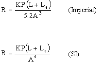
Atkinson Equation
Select this option to calculate the resistance value by using the Atkinson equation. There are two forms of Atkinson's Equation based on the system of units used.
|
Value |
Description |
|---|---|
|
K |
Refers to an empirically determined friction factor. |
|
P |
Refers to the perimeter of the airway. |
|
L |
Refers to the length of the airway. |
|
A |
Refers to the area of the airway. |
|
Le |
Refers to an equivalent length (empirically determined) used to account for shock losses due to changes in the airway shape and/or obstructions in the airway. |
|
R |
Refers to the resulting resistance value. |
R=p/Q^2
Select this option to calculate the resistance by basing it on head loss and flow (Square's Law).
The following equation is used for the calculation:
![]()
|
Value |
Description |
|---|---|
|
p |
Refers to the pressure drop (head loss) in the branch. |
|
Q |
Refers to the flow through the branch. |
|
R |
Refers to the resulting resistance value. |
Density
Enter the air density value for the ventilation branch.
Branch Static Pressure
The static pressure of the chosen branch can either be entered ( Known ), or calculated ( XNVP= Ro * delta E * g ).
![]()
|
Value |
Description |
|---|---|
|
R0 |
Refers to the air density. |
|
|
Refers to the change in elevation from the start to end node. |
|
g |
Refers to the gravitational acceleration. |
|
XNVP |
Refers to the resulting static pressure value. |
Flow Type
Unregulated
Select this option to define the branch as having no known information as to the airflow.
Fixed Quantity
Select this option to apply a fixed airflow quantity to the branch. The value entered refers to the amount of air that should be flowing through the branch.
Fan
Select this option to assign a fan to the branch. You will need to nominate the appropriate fan file (.vfn) and fan name.
Inflow
Select this option to enter an inflow value. The inflow value needs to be entered as units in flow. An inflow is used in cases where the ventilation network of interest is a subset of an overall network. This inflow is a nodal characteristic due to the flow of air from the 'master' network into the subset. If only one branch is connected to this inflow node, then the flow through the branch will be the same as the inflow.
However, if there are several parallel branches connected to this node, then the flow through these branches will be determined by other parameters, that is, resistance etc.
Note: A network can contain an unlimited amount of inflow branches.
Contaminant
Select this option to enter a contaminant value. The contaminant value needs to be entered as units in flow.
Click OK.
The ventilation branch is then created in the current ventilation layer.
If you haven't defined the arrow defaults (through the Defaults : Arrow section of the Tools > Preferences option), then the Arrow Attributes panel displays before the branch is created. If you try to cancel out of the Arrow Attributes panel, you will be prompted that this information is required, and you will be returned to the Arrow Attributes panel. When you are finished entering arrow attributes, select OK to continue.
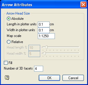
Figure 1 : Arrow Attributes panel
Absolute Size
Select this option if you want the arrow's head to have a fixed size. You can then specify the arrow length in plotter units, the arrow width in plotter units and the map scale for this size (this is the scale used in drawing the arrow head on the screen).
Relative Size
Select this option if you want the arrow's head to have a size relative to the length of the arrow instead of an absolute size. The longer the arrow, the bigger the arrow's head.
The arrow head length and width can either be entered as a percentage (of the arrow length), or it can be specified through using the available slider bars.
Fill
Select this check box to fill the arrow head with a solid pattern. If this check box is not checked, then the arrow head will be open.
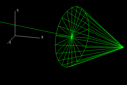
Figure 2 : An Unfilled 3D Arrow
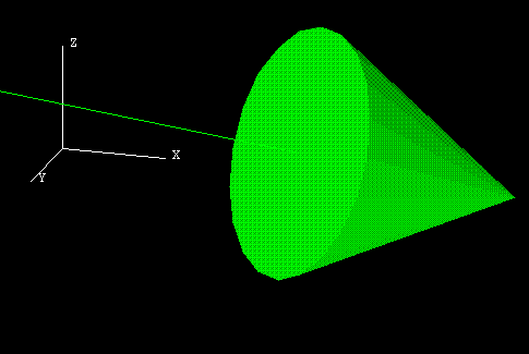
Figure 3 : A Filled 3D Arrow
Number of Facets
Enter the number of facets in the arrow head's cone (a minimum of 3 and a maximum of 100). The higher the number of facets, the more the arrow head approximates a cone.
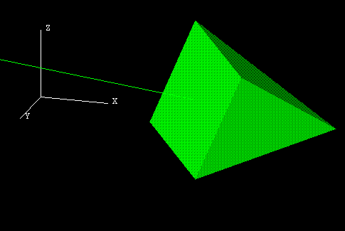
Figure 4 : 3D Arrow with 4 Facets
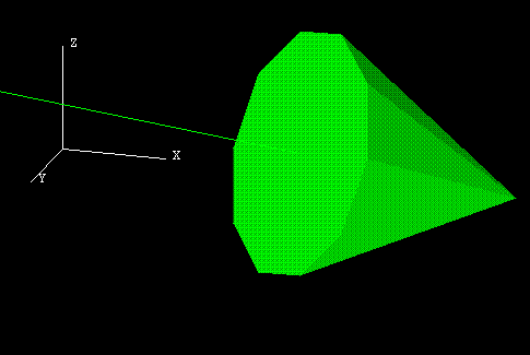
Figure 5 : 3D Arrow with 10 Facets
Figure 6 : 3D Arrow with 20 Facets
Select OK.
You will then be prompted, depending on the option chosen through the Create Branch dialog box, to either indicate the first point or select the line to copy.
Cancel to return to the Create Branch dialog box. Cancel again when you have finished creating ventilation branches.
Use the Edit Branch option if you want to edit the parameters of an existing branch, or the Edit All Branches option to edit all of the branches in the current ventilation network.

