Section
View a Cross-Section
Use the Section option to set a cross-sectional 3D view with a specified dip and width of view. The dip and width will be stored in the <proj>envis.defaults file.
This option creates a "primary section". It is only possible to have one primary section at a time, any newly created primary section will replace the existing one. If you want to create multiple sections (non-primary), then use the View > Create Section option (which you can also use to create primary sections) or the Create Section icon ![]() on the Standard toolbar.
on the Standard toolbar.
An Overview Window can be opened (using the Show Overview ![]() icon on the Graphics toolbar) to show the plan location of the cross section.
icon on the Graphics toolbar) to show the plan location of the cross section.
Instructions
On the View menu, point to Change View, and then click Section to display the Create Primary Section panel.
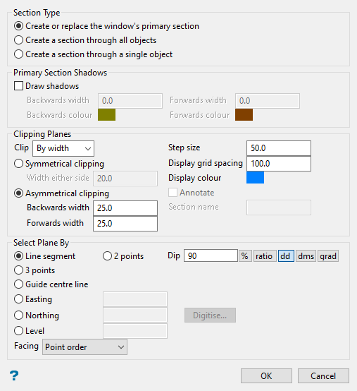
Primary Section Shadows
Draw Shadows
Select this check box to shadow the data that falls outside the section. Shadows are only displayed if you choose to clip By width.
The following options are only accessible when the Draw Shadows check box is enabled.
Backwards width/Forwards width
Specify the width of data that will be shadowed out either side of the section. The backwards width and the forwards width do not have to be the same value.
Backwards colour/Forwards colour
Specify the colour of the backwards and forwards shadows.
Clipping Planes
Clip
Specify the type of clipping plane to be used with the section. There are four options: By width, Forwards, Backwards or No clipping.
If you select By width, then the view of your section will only include the width of the section (plus any shadows if you have created a primary section). If you select Forwards, then the view of your section will include everything in front of your section. If you select Backwards, then the view of your section will include everything behind your section. If you select No clipping, then the view of the section will include everything.
For more information see Clipping Planes .
Step size
Enter the distance that is moved each step when moving the section through space. To move the section through space, use the Slice Forward ![]() or Slice Backwards
or Slice Backwards ![]() icons on the Slice toolbar.
icons on the Slice toolbar.
Alternatively, you can also select the Align View With Current Slicing Plane icon ![]() on the Slice toolbar and use the up and down arrows to move through space.
on the Slice toolbar and use the up and down arrows to move through space.
Symmetrical clipping/Asymmetrical clipping
When you choose to create a section By width you can specify that the section is symmetrical, that is, same distance forwards or backwards, or asymmetrical, that is, different distance forward and backwards.
Display grid spacing
Enter the spacing of the grid used to represent the plane. To control the display of the grid, whether it is visible or invisible, use the Display slider bar on the Slice toolbar.
See Clipping Planes for diagrams showing displayed grids.
Display colour
Specify the colour of the grid used to represent the plane.
Annotate
Select this check box to annotate a point on the section plane. The annotation value will change as you move the section through space. The size of the annotation is directly proportional to the Display Grid Spacing setting.
Section Name
Enter the name of the section. This name will be displayed in the drop-down list on the Slice toolbar.
Line segment
Select this option to define the plane by selecting an existing line and specifying the dip. Only design strings may be picked and it is not possible to pick a line in an underlay. The direction of the view, and therefore the direction of the stepping, depends on the digitised sequence of the line. The digitised sequence of the line can be reversed using the Design > Object Edit > Reverse option.
2 Points
Select this option to define the plane by digitising two points and specifying the dip. To locate a point precisely, use the Snap to Objects ![]() or Snap to Points
or Snap to Points ![]() modes on the Digitise toolbar. Points may be snapped onto underlays, such as block model slices or triangulations. If you use Indicate mode
modes on the Digitise toolbar. Points may be snapped onto underlays, such as block model slices or triangulations. If you use Indicate mode ![]() to select the points, then the points have the current default Z value.
to select the points, then the points have the current default Z value.
Dip
If you choose to select your plane by either a line segment or 2 points, then you must indicate a dip. The dip is the angle of the section from horizontal. Valid dip angles are between -90 and 90.
3 Points
Select this option to define the plane by digitising 3 points. To locate a point precisely, use the Snap to Objects ![]() or Snap to Points
or Snap to Points ![]() modes on the Digitise toolbar. Points may be snapped onto underlays, such as block model slices or triangulations.
modes on the Digitise toolbar. Points may be snapped onto underlays, such as block model slices or triangulations.
Selecting this option to define explicitly the location and orientation of a plane by indicating 3 points. The first two points define the bearing of the plane, and the third point defines the dip of the plane.
Guide centre line [section is normal to line]
Select this option to define the plane by selecting a centre line. W tag of the points of the picked centre line can be employed to pass section width.
To achieve the best results for the following three methods, Easting, Northing and Level, use the Zoom Data Extents icon ![]() on the Graphics toolbar, which allows all of the graphics to be viewed.
on the Graphics toolbar, which allows all of the graphics to be viewed.
Easting
Select this option to enter a specific Easting value (X value). There are two ways to enter the Easting value; you can enter it directly into the text box, or you can select the Digitise icon, which to select a point from the viewing window. The resulting section has a constant Easting (X) value.
You will be facing in an easterly direction when defining the section view.
Northing
Select this option to enter a specific Northing value (Y value). There are two ways to enter the Northing value; you can enter it directly into the text box, or you can select the Digitise icon, which to select a point from the viewing window.
The resulting section has a constant Northing (Y) value.
Level
Select this option to enter a specific Level value (Z value). There are two ways to enter the Level value; you can enter it directly into the text box, or you can select the Digitise icon, which enables you to select a point from the viewing window.
The resulting section has a constant Level (Z) value.
To locate a point precisely, use the Snap to Objects ![]() or Snap to Points
or Snap to Points ![]() modes on the Digitise toolbar. Points may be snapped onto underlays, such as block model slices or triangulations. You will need to select this point before completing the panel. The panel will collapse while you select the point.
modes on the Digitise toolbar. Points may be snapped onto underlays, such as block model slices or triangulations. You will need to select this point before completing the panel. The panel will collapse while you select the point.
Facing
Select the orientation of the section view. The drop-down list contains different options depending upon what method was used to select the plane (see table below). The first choice in the drop-down list is the default orientation.
| Method | Orientation |
|---|---|
| Line Segment | Point Order Reverse Point Order |
| Two Points | Left to right Right to left |
| Three Points | Clockwise Anticlockwise |
| Guide centre line | Point Order Reverse Point Order |
| Easting | East West |
| Northing | North South |
| Level | Down Up |
Click the Auto ![]() button to display the Section specification panel.
button to display the Section specification panel.
Section list
Select the Section list from the drop-down menu.
Definition section
Click Definition section to display the Section definition panel.
Click OK.
You can toggle between a view of the section and the loaded object by using the Slice Properties icon ![]() on the Graphics toolbar. Alternatively, you can also use the S key to toggle between the views.
on the Graphics toolbar. Alternatively, you can also use the S key to toggle between the views.

