Specifications
Pattern specifications
Instructions
Follow these steps:
-
On the Drill and Blast menu, point to Files, then click Specifications.
-
Select Pattern specifications from the Specifications panel, then click OK to display the Pattern specifications panel.
-
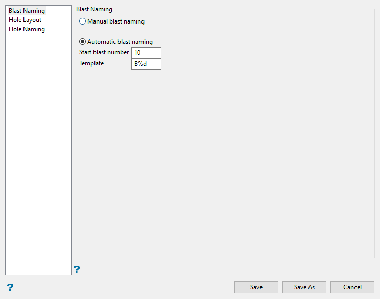
Select whether you want to use automatic or manual naming when creating a new blast.
-
Manual blast naming - Select this option to manually assign the blast name when creating a new blast. If you have chosen to manually assign the blast name, then the field on the Blast naming panel will be left blank when you attempt to create a new blast.
-
Automatic blast naming - Select this option to automatically assign the blast name when creating a new blast. You will be required to enter a start number as well as a blast name template. The template can either be text only (in which case the blast number is added to the end of the name) or it can be a combination of text plus the
%dformat string (where%d= an incrementing blast number).Example: If you assigned a start blast number of
1, and entered a template ofB%d, then the following blast name will be assigned. This value will be incremented by 1 for each blast created, that is,B2,B3,B4, etc.
-
-
Proceed to the Hole Layout tab
Hole Layout
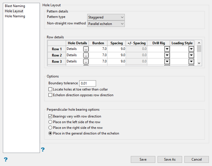
Use this section to define the pattern and row details for newly created blasts.
Follow these steps.
-
Set the pattern details. This section determines if the holes and rows of a blast are positioned as a square, staggered, or equilateral.
-
Select the non-straight row method. This determines how the pattern behaves if corners are encountered when creating rows. You can choose either meshed or parallel echelon.
In general, parallel echelon is used for small angle changes in the rows while meshed works better for larger angles.
Note: Due to geometric constraints, using an equilateral pattern to design non-straight holes will produce poor results.
-
Use the Row details table to determine how the holes in each row are to be created, as well as the distance between each hole.
-
Hole Details - Select the
 button to display the Hole Design and Display panel.
 Hole Design and Display panel
Hole Design tab
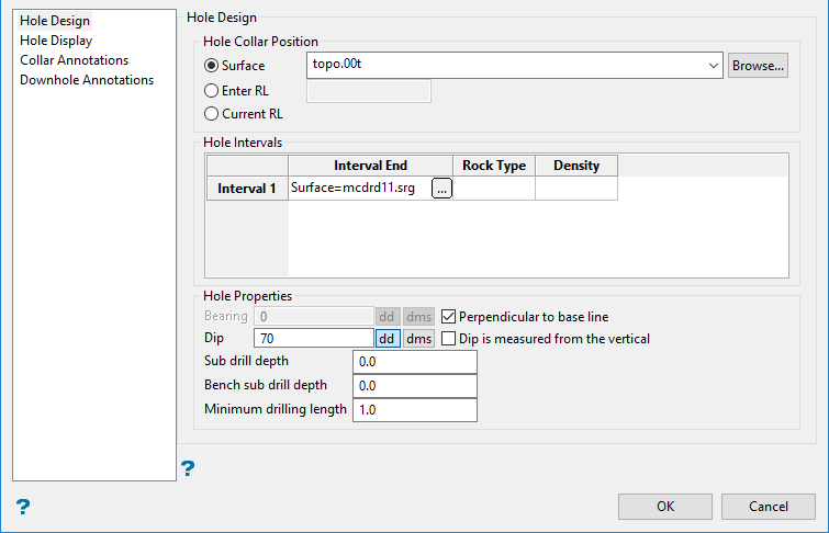
The Hole Design tab is used to enter design information such as the start position, hole dip, and direction.
Follow these steps.
-
Select the Hole Start Position. There are three options:
-
Surface (grid or triangulation) - The drop-down list contains all grids and triangulations found in your current working directory. Click Browse to select a file from another location.
-
Enter RL - Enter an elevation value.
-
Current RL- The elevation value of the current blasthole.
-
-
Set the Hole Intervals.This defines the intervals that the holes intersect. Intervals run from the start of the hole or from the previous interval to the interval end.
To define an interval, select the
button to display the Define end of interval panel.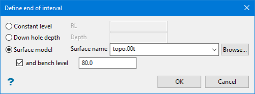
This panel defines a geological interval, which can either be set as an RL value, a down hole depth, a position (either top or bottom) or an existing surface.
The Surface drop-down list contains all grids and triangulations found in your current working directory.
If the and bench level check box is checked, you can enter the bench level in the numeric field. This bench level will limit the depth of the intercept.
For the case above, if the hole intercepts bench level 80 before intercepting topo.00t, then the intercept will be moved up to level 80.
-
Set the hole properties. This defines the bearing, dip, sub drill, and minimum drilling length.
Both the Bearing and Dip values can be entered using decimal degrees or degrees minutes seconds. Select the appropriate option and enter the value. If you select a different angle format option, the value entered in will be converted to the new format.
Enable Perpendicular to base line if you want the bearing to be at right angles to the baseline. If this check box is checked, then the Bearing field will be unavailable. You will also be required to digitise a baseline when using the Create Holes at Points and Create Holes along Line options.
-
Enter the Sub drill depth. This value refers to the depth past the final interval. A positive value will cause the hole to travel the same distance past the final interval, while a negative value will stop the hole with a standoff above the surface. If zero is entered, then the hole will stop at the surface.
-
The Bench sub drill depth is only applied to a hole toe that has been intercepted with a bench level. It will only be fully applied if the final position of the toe is above the position it would have taken based on the surface and the standard sub drill depth. For example, if you standoff coal and subdrill on the bench, the toe will never go below the standoff position from the surface. The bench subdrill can be edited using a right-click menu option under the Edit Hole menu. It can also be edited using the Edit Holes panel.
-
Enter the Minimum drill length interval that will be considered.
Hole Display tab
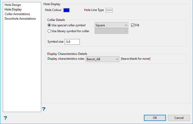
The Hole Display tab is used to set the display characteristics for the blast holes.
Follow these steps.
-
Select the colour and line type by clicking on the icons.
-
Set the symbols that will be used to display the collars in the Collar Details section.
Selecting Use special collar symbol will allow you to choose between a square, circle, or cross.
Selecting Use library symbol for collar will allow you a much larger selection taken from the symbols database.
Set the Symbol size in the space provided.
-
Select any Display Characteristics Details you want to apply. These options are set up using the Display characteristics settings on the Drill ad Blast Specification panel.
Collar Annotations tab
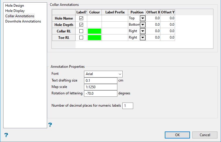
The Collar Annotations tab is used to set up the labels associated with the blasts.
Follow these steps.
-
Use the table to determine which labels will be visible and where they will be located.
-
Label - Use the checkbox to select which label will be displayed.
-
Colour - Click the table cell to display the colour palette.
-
Label Prefix - Enter any text you want to use as a prefix.
-
Position - Use the drop-down list to select the position of the label.
-
Offset X/Y - Enter the distance away from the collar that you want the label to display.
-
-
Set the Annotation Properties for the text. These determine how the labels will look.
Downhole Annotations tab
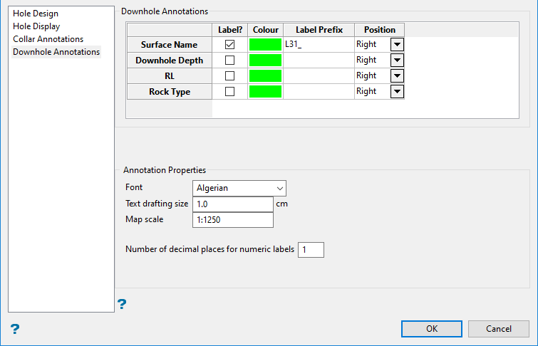
The Downhole Annotations tab is used to set up labels that will be displayed at the bottom of the drillhole.
Follow these steps.
-
Use the table to determine which labels will be visible and where they will be located.
-
Label - Use the checkbox to select which label will be displayed.
-
Colour - Click the table cell to display the colour palette.
-
Label Prefix - Enter any text you want to use as a prefix.
-
Position - Use the drop-down list to select the position of the label.
-
-
Set the Annotation Properties for the text. These determine how the labels will look.
-
-
Burden - Enter the distance between adjacent rows. This value is not required with equilateral patterns.
-
Spacing - Enter the distance between each hole of a single row.
-
+/- Spacing - Refers to the tolerance value that will be used to move holes along rows when corners are encountered. This value can only be entered when using meshed patterns.
-
Drill Rig - Select a drill rig library. The drop-down list contains all of the drill rigs that are defined in your Drill and Blast specifications file (specifications.dab).
-
Loading Style - Select the loading style specification that you want to use. The drop-down list contains all of the loading styles that are defined in your Drill and Blast specifications file (specifications.dab).
-
-
Enter the Boundary tolerance value. This optional value will be used to create holes that would have previously been disregarded as they fell outside of the boundary. If a hole falls in the specified tolerance value, and is outside of the boundary, then it will be created on the boundary polygon at the nearest point.
-
Select Locate holes at toe rather than collar to create holes using a boundary and a reference point, which is digitised at the toe of the holes. The holes are then projected from the toe up to the collar surface, thus enabling the toes to created along a straight line.
-
Select Echelon direction opposes row direction to reverse the echelon direction.
-
Select Bearings vary with row direction to honour the row direction when using perpendicular bearings.
If you are using perpendicular bearings with multi-segment rows, and the Bearings vary with row direction check box has been enabled, then the bearings will be perpendicular to the row direction at the hole's location. If this check box is not checked, then all perpendicular bearings will be based on the direction of the nominated base line.
This section also includes options for left/right perpendicular bearings (based on the direction of the base line). If the option is set to the echelon direction option, which was the default behaviour in earlier versions, then it will default to the right side if using the 'holes at points' or 'along line' options (where there are no echelons).
Hole Naming
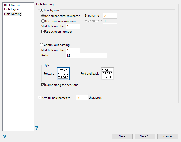
The Hole Naming section controls how each hole in each row is named.
Follow these steps.
-
Select whether you want to name the holes on a row by row basis or using continuous naming.
-
Row by row - Select this option to assign a different prefix to each row and restart the numbering when naming the following row.
Select wither Use alphabetical row name or Use numerical row name.
Use alphabetical row name - For example,
A1,A2,A3etc. You will need to specify the start row name for the first row, as well as the start hole number, that is, the number of the first hole in the row. Holes named using this method will be assigned to groups based on the row name.All holes in row A are assigned to group A, while all holes in row B are assigned to group B.
Use numerical row name - Select this option to use numerical row names, For example,
1,2,3etc. You will need to specify the start hole number.Select Use echelon hole naming if you want to adjust the hole numbering for the rows so that the numbers follow echelons. If this option is enabled, then the holes will be named according to the hole name located in the row diagonally above, in an oblique or step-like formation.
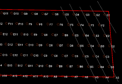

The figure on the left shows Echelon hole naming enabled, with the holes running along the white lines in a sloping direction.
The figure on the right shows Echelon hole naming not enabled, where the first hole in each row is always a one hole, for example
A1,B1,C1,D1etc. -
Continuous naming - Select this option to use continuous naming when assigning the hole names. You will be required to specify the start hole number and prefix, as well as select the naming style.
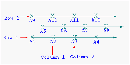
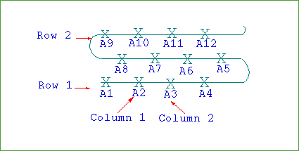
The figure on the left show the Forward Hole Naming Style. The figure on the right shows the Forward and Back Hole Naming Style.
Select Name along the echelons if you want continuous naming to run along the echelon instead of the row.
-
-
Select Zero fill hole names to ... characters if you want to use zeroes to fill in the hole names. You will need to specify the number of characters that you want to use. If you specify that you want to use 3 characters, then A1 will become A001 and A21 will become A021.

