Graded Contour
Use this option to create a line with a given gradient between two points, a starting point and an ending point. You can select the two points by clicking on an existing surface triangulation, or by using a layer that contains at least two polylines (such as those showing elevation contour lines of a topographic surface.) The line will be automatically generated and will continue until the specified length is reached or the gradient is too steep or shallow to continue.
Instructions
On the Model menu, point to Contouring, and then click Graded Contour.
Follow these steps:
-
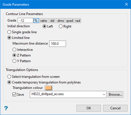
Enter the gradient into the Grade textbox. It can be entered as a percentage (-12%), as a ratio (-1:8.333), in degrees (-6.84), as dms (-6.50.33.984), as gradians (-7.603383), or as radians (-0.119434). Positive numbers apply an upward gradient from the start point, whereas negative numbers apply a downward gradient.
Tip: The units of measurement are automatically converted from one to another each time you click on a unit selection.
-
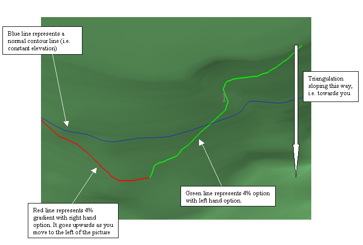
Select an Initial direction of either right or left. To determine which way the line will generate, think of moving along the strike line with the higher side of the plane on the side that you have chosen (i.e. if you chose right, then the plane on the right side of the strike line will be higher). If the gradient is positive, then the line will climb up the slope as you move. If negative, then the line will climb down the slope.
-
Select either Single grade line or Limited line.
A single grade line will continue until it reaches the edge of the triangulation, or the selected gradient lies outside the plane of the next triangle facet.
For a limited line, enter a value for the Maximum line distance. This will be the maximum true 3D line length, unless the line terminates prematurely because the selected gradient lies outside the plane of the next triangle facet.
There are also three line pattern options to choose from:
 Interactive
Select this option to produce a gradient line with a constant slope.
 Z Pattern
Select this option to produce a limited length line that obeys the initial direction. Once it has reached the maximum extent, it will reverse direction and continue to produce another limited line length. It will then reverse direction again, and keep repeating until it reaches the edge of the triangulation, or facet gradients prevent it from continuing. This option could be used as a basis for designing constant gradient roadways that need to switchback up or down a slope.
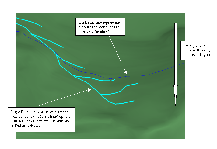
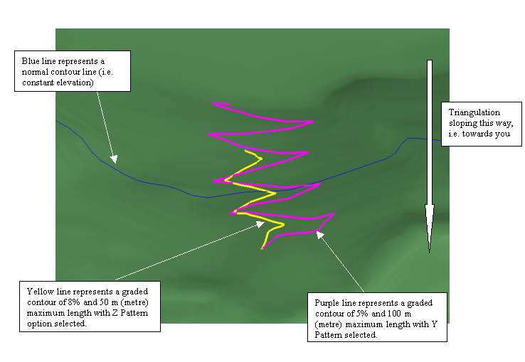 Y Pattern
Select this option to produce a line that extends to the edge of the triangulation or until facet gradients prevent continuation. Additionally, for every maximum length distance, a spur line at the same gradient will be created running in the opposite direction to the main line. The length of these spur lines is the maximum length.
-
Select the method you want to use to locate your start points.
Note: With both methods, you will need to have your data already loaded into Envisage.
Method One - Select triangulation from screen
With this method, you will pick a starting and ending point by clicking on the surface triangulation. A line will be automatically generated following the gradient and distance parameters input in the panel. You can click multiple starting points to create multiple lines. Each line will be added to the layer you selected as your active layer.
Method Two - Create temporary triangulation from polylines
This method allows you to create a temporary triangulation from two polylines, such as those selected from a layer showing contour intervals. This is useful if you need to zoom into an area, or if you want to create a graded contour line with more detail than would be possible using just a surface triangulation that is much larger.
-
Click OK.
-
If you are using Select triangulation from screen, select the triangulation on which to base the graded contour. If there is only one model currently loaded onscreen, then it will be automatically selected.

Figure 1: Creating a graded contour from an existing surface triangulation. A graded contour line can be created from any location as long as the input parameters can be followed. If you click a location in which a line would exceed the grade parameters, an error message will be displayed stating that the line cannot be create. (See next image.)
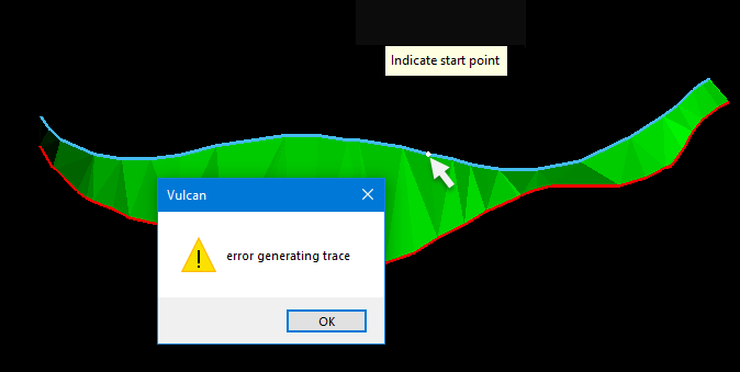
Figure 2: Error in generating trace due to grade parameters being exceeded.
If you are using the method Create temporary triangulation from polylines, Select the two lines that will be used to create the temporary triangulation. A surface triangulation will be create from the two lines. Click on triangulation or poly lines to select the starting point for the graded contour. A new graded contour will be created following input parameters you entered on the main panel.
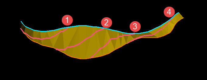
Figure 3: Four graded contour line were created from different starting points.
Note: If the Snap to Points
 or Snap to Objects
  modes (found on the Digitise toolbar) are not used to select the starting point of the graded contour, then the line will start at the default Z value. If the Z value is not set to the same elevation as your intended starting point, this may cause undesirable result.
When to graded contour lines appear on the screen, their colour will be the current default colour, which displays on the Status toolbar.
-
Right-click to cancel the operation, or to exit when you are finished.

