Create a Vein Model
Vein modelling is a method of modelling stratigraphic horizons as continuous surfaces. The ![]() Vein Model tool can generate a continuous solid or set of surfaces representing the vein or stratigraphic horizon.
Vein Model tool can generate a continuous solid or set of surfaces representing the vein or stratigraphic horizon.
Follow these steps to create a vein model from your drillhole data:
-
Launch the Vein Model tool.
On the ribbon, navigate to Modelling > Vein Modelling >
 Vein Model.
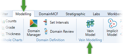
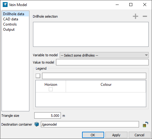
The Vein Model panel appears.
-
Supply the data to model.
The vein model tool will model a single vein from supplied source data. You can supply drillholes, CAD data, or both.
Supplying drillhole data
To supply drillholes as source data:
-
Switch to the Drillhole data tab if it is not already active.
-
In the Drillhole selection list, specify the set of drillholes to base the model on.
 Expand for detailed instructions.
This field requires a drillhole selection from a single database.
-
Add a drillhole database
 or drillhole
  subset to the list by making a selection in the project explorer and then clicking
  . Alternatively, drag and drop the drillhole database or selection directly from the project explorer into the drillhole list.
-
Remove an item by selecting it in the list and clicking
 .
.
-
-
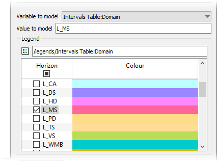
From the Variable to model drop-down, select the table and field for the variable you want model. To model your domains, select Intervals Table:Domain.
-
Specify the value you want to model. Either:
-
Type the name of the value in Value to model.
-
If there is a compatible legend for the variable you want to model, make sure it is specified under Legend. Then, select the checkbox for the value from the Horizon column.
-
Supplying CAD data
You can supply CAD data representing hanging walls and footwalls. The CAD data can be any object containing points, such as point sets
 , lines
  , or polygons
  . Only the points extracted from these objects will contribute to the model.
To supply CAD data:
-
Switch to the CAD data tab.
-
Under Hanging wall data, specify any number of objects representing the hanging wall.
-
Under Footwall data, specify any number of objects representing the footwall.
-
Configure the remaining options as follows:
-
Show trend plane—select this checkbox to show a transient trend plane in the view.
-
Flip the hanging wall and footwall—select this checkbox to invert the meaning of the hanging wall and footwall.
-
Choose a colour for the hanging wall and the footwall from the Hanging wall and Footwall colour pickers.
-
-
-
Specify controls.
Additional controls are available to constrain the vein model in various ways.
To configure additional controls, switch to the Controls tab.
Extent limits
Under Extent limits, you can configure the limits of the model in the XY plane.
-
Under Relimiting, choose one of the following options:
-
No relimiting—the model will extend laterally to fill a rectangular area aligned to the X and Y axes, roughly covering the extent of the input data.
-
Relimit to input data—the model will extend laterally to the shape of a convex polygon fitting the input data in the XY plane.
-
Relimit to polygon—the model will be extend laterally to the shape of the supplied polygon in the XY plane.
-
-
Extrapolation distance allows you to extrapolate the model past the relimit constraints set above by the specified distance.
Drillhole ends
Under Drillhole ends, you can control the modelling behaviour where intervals of the target value occur at the top or the bottom of a drillhole. This is to account for cases where the drillhole data is incomplete, in which case you might like to ignore the interval.
Choose how to classify matching intervals occurring at the top or the bottom of the hole, either as:
-
on the surface boundary—i.e. make the model honour the interval.
-
inside the surface—i.e. ignore the interval.
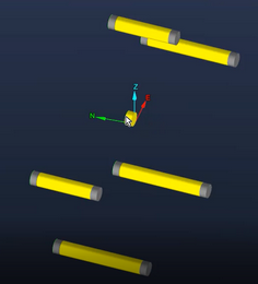
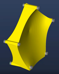
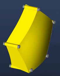
The diagram to the right will update to indicate the effect of your choice.
Consider the example below. The first frame shows several drillholes, with the target interval coloured yellow. The drillhole in the centre has a single, short interval which may be incomplete. The second frame shows the resulting model if the interval is specified as being on the surface boundary. The model pinches in to honour the data exactly. The third frame shows the resulting model if the interval is specified as being inside the surface, in which case it is ignored, and the surface is modelled on the trending drillhole intervals.
-
-
Configure the output.
Configure which objects to generate on the Outputs tab:
-
Vein solid—select this checkbox to generate a solid surface representation of the vein model.
-
Surfaces—choose whether to generate surface representations of the hanging wall, footwall and/or middle of the vein, coloured with the specified colours.
-
Data points—choose whether to generate point sets of the hanging wall, footwall and/or middle of the vein.
At the bottom of the panel, set Triangle size to change the maximum triangle size on any generated surfaces. A smaller triangle size will result in a higher resolution model that better conforms to thinner domains.
In the Destination container field, optionally change where the output is to be saved. The default destination is /geomodel.
-
-
Generate the Model.
Click OK or Apply to generate the vein model.
|
Create an Implicit Model
|