Surfaces
The Surface group of the Create ribbon contains tools to generate surfaces from different data sources.
Surface generation allows you to visualise discrepancies in a dataset for a single variable. You can generate surfaces from both hole and blast data. BlastLogic saves the generated surfaces to the cad container which is located in the data explorer.
 Surface From Holes
The Surface From Holes tool allows you to generate a surface from a selection of holes.
To generate a surface from a selection of holes, follow these steps:
-
Select the desired holes in the view window or data explorer.
-
On the Create ribbon, in the Surfaces group, select
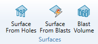
Surface From Holes. The Surface From Holes panel will appear.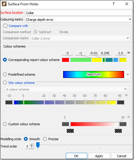
-
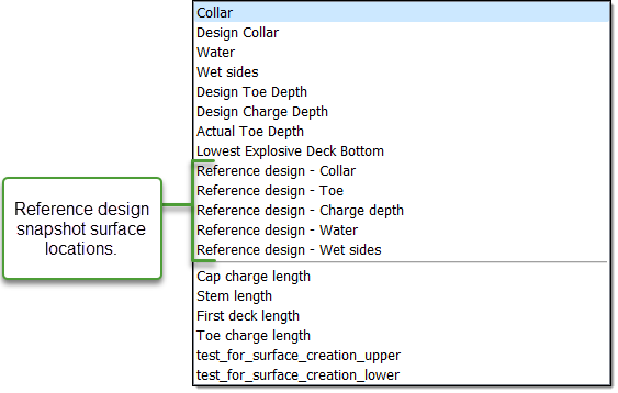
Select a surface location or down-hole property from the Surface location drop-down.
Tip!You can also select reference design snapshot surface locations from this drop-down menu.
 Expand for more information on the surface location
The surface location defines the z-value at which the surface appears. A hole dataset which has similar surface location values will appear relatively flat, whereas a surface with significantly different surface location values will have an uneven surface.
-
Select a colouring variable from the Colouring metric drop-down.
Expand for more information on the colouring metric
The colouring metric is a variable which sets how BlastLogic will colour the surface. For example, say you set the colouring metric to variable X, where X is a shared attribute amongst a selection of holes. The following outcomes can occur:
-
If there is great variation in X between the holes, then the surface will be varied in colour.
-
If there is little variation in X between the holes, then the surface will have fewer colours.
-
-
Optionally, select the Compare with checkbox. In this section, you can select a Comparison method and a Comparison metric.
-
Select the radio button of the desired colour scheme in the Colour schemes section. You can choose from the following colour schemes:
-
Corresponding report colour scheme
This option is only available for colour metrics previously set in the report setup tab of the site setup panel. To open the site setup panel, on the Home ribbon, in the Setup group, select Site. For more information on setting report colours, refer to the Report setup section of the setup page. -
Predefined scheme
This option allows you to select from pre-made colour schemes stored in BlastLogic. Select the desired scheme from the Spectrum drop-down. -
Site colour scheme
This option allows you to select from colour schemes you (or other users) have previously defined. You can define these schemes in the custom colour schemes tab of the site setup panel tool. To open the site setup panel, on the Home ribbon, in the Setup group, select Site. Refer to the Custom colour schemes section of the setup page for information on creating custom colour schemes.Note:The site colouring scheme should have the same units as the selected colouring metric.
-
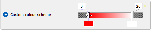
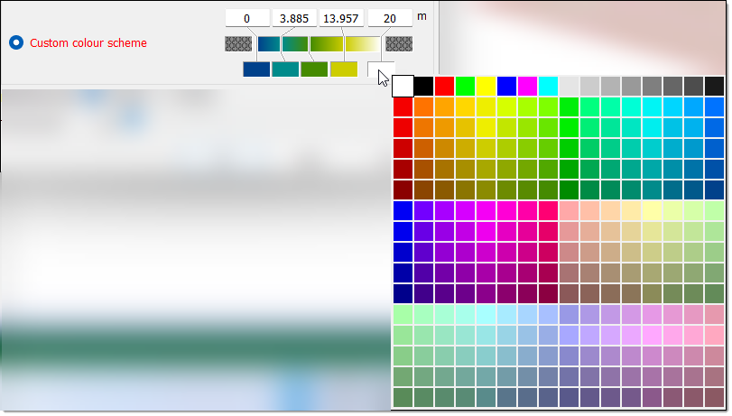
Custom colour scheme
This option allows you to design a new custom colour scheme. To do this, follow these steps:-
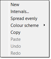
Right-click on the colour band. The following context menu will appear.
-
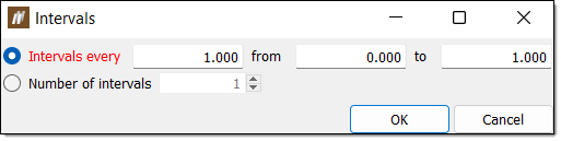
Select Intervals.... The Intervals panel will appear.
-
Select either Intervals every or Number of intervals using the corresponding radio buttons.
-
Enter the desired intervals.
-
For Intervals every, enter the space between intervals along with the starting and end points in the associated fields.
-
For Number of intervals, enter the number of intervals in the associated field.
-
-
Click OK
Expand for an alternative boundary setting method.
You can also use the following method to set additional boundaries:
-
Move the mouse to the edge of the colour band such that the cursor changes to a horizontal resize cursor and click.
-
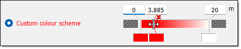
Drag the cursor to the desired boundary position. Continue this process until you have defined the necessary boundaries.
 Tip!
Tip!Click
 above a boundary to delete it.
-
-
Set the boundary colours. You can do this in either of the following ways:
-
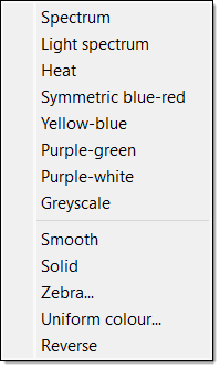
Right-click on the colour band and hover over the Colour scheme option in the context menu. Select the desired colour scheme from the list.
-
Select the colour block corresponding to a boundary and select the desired colour from the colour palette.
-
-
-
-
Select the appropriate modelling style via the Modelling style radio buttons. There are two modelling styles to select from:
-
Smooth
In this case, you can also alter the trend order using the Trend order slider as desired. -
Precise
In this case, you can also select the Manual maximum edge length checkbox and enter a length in the Length field.
Expand for more information on modelling styles
There are two modelling styles you can select:
-
Smooth
The smooth modelling style creates a surface using interpolated data. For smooth modelling, a trend order is set. This trend defines the extent of approximating that BlastLogic will perform. The greater the trend order, the smoother the surface. -
Precise
The precise modelling style creates a surface at the exact points without any approximations. For precise modelling, you can set a manual maximum edge length.
In general, BlastLogic generates a surface from a collection of triangulations using an algorithm. This algorithm treats triangulations at the edge of the surface as outliers and removes them to create a more representative object. Triangulations are removed based on their edge length, which BlastLogic automatically calculates. However, you can override using the manual maximum edge length. As a result, any triangulation at the boundary with an edge greater than the manual maximum edge length will be removed from further calculations.
-
-
Click OK or Apply. BlastLogic saves the surface to the cad container in the data explorer.
 Surface From Blasts
The Surface From Blasts tool allows you to generate surfaces from a selection of blasts.
To generate a surface from a selection of blasts, follow these steps:
-
Select the desired blasts in the data explorer. BlastLogic will create a surface for each blast you select.
-
On the Create ribbon, in the Surfaces group, select
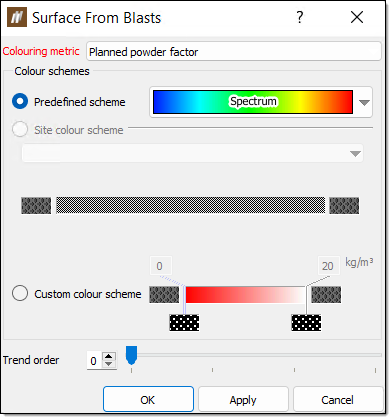
Surface From Blasts. The Surface From Blasts panel will appear.
-
Select a colouring variable from the Colouring metric drop-down.
Expand for more information on the colouring metric
The colouring metric is a variable which sets how BlastLogic will colour the surfaces. For example, say you set the colouring metric to variable X, where X is a shared attribute amongst a selection of blasts. The following outcomes can occur:
-
If there is great variation in X between the blasts, then the resulting surfaces will be varied in colour.
-
If there is little variation in X between the blasts, then the resulting surfaces will have less colour variation.
-
-
Select the radio button of the desired colour scheme in the Colour schemes section. You can choose from the following colour schemes:
-
Predefined scheme
This option allows you to select from pre-made colour schemes stored in BlastLogic. Select the desired scheme from the Spectrum drop-down. -
Site colour scheme
This option allows you to select from colour schemes you (or other users) have previously defined. You can define these schemes in the custom colour schemes tab of the site setup panel tool. To open the site setup panel, on the Home ribbon, in the Setup group, select Site. Refer to the Custom colour schemes section of the setup page for information on creating custom colour schemes.Note:The site colouring scheme should have the same units as the selected colouring metric.
-
Custom colour scheme
This option allows you to design a new custom colour scheme. To do this, follow these steps:-
Right-click on the colour band. The following context menu will appear.
-
Select Intervals.... The Intervals panel will appear.
-
Select either Intervals every or Number of intervals using the corresponding radio buttons.
-
Enter the desired intervals.
-
For Intervals every, enter the space between intervals along with the starting and end points in the associated fields.
-
For Number of intervals, enter the number of intervals in the associated field.
-
-
Click OK
Expand for an alternative boundary setting method.
You can also use the following method to set additional boundaries:
-
Move the mouse to the edge of the colour band such that the cursor changes to a horizontal resize cursor and click.
-
Drag the cursor to the desired boundary position. Continue this process until you have defined the necessary boundaries.
Tip!Click
above a boundary to delete it.
-
-
Set the boundary colours. You can do this in either of the following ways:
-
Right-click on the colour band and hover over the Colour scheme option in the context menu. Select the desired colour scheme from the list.
-
Select the colour block corresponding to a boundary and select the desired colour from the colour palette.
-
-
-
-
Optionally, set the trend order using the Trend order slider. This trend defines the extent of approximating that BlastLogic will perform. The greater the trend order, the smoother the surface.
-
Click OK or Apply. BlastLogic saves the surface to the cad container in the data explorer.
 Blast Volume
To generate a blast volume object, follow these steps:
-
Select the desired holes or blast in the view window or data explorer.
-
On the Create ribbon, in the Surfaces group, select
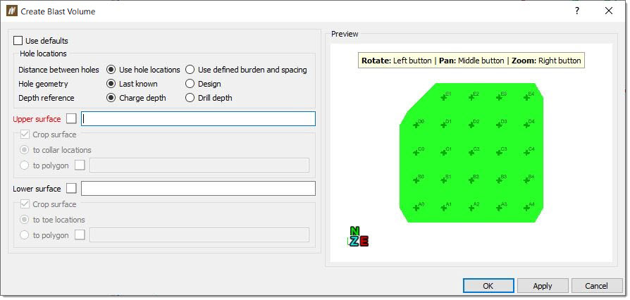
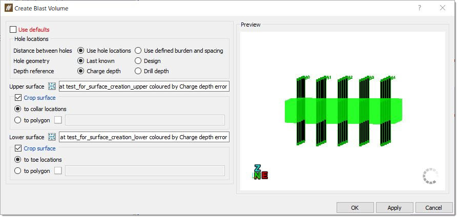
Blast Volume.The Create Blast Volume panel will appear.
-
Configure the volume settings. You can either:
-
Select the Use defaults checkbox. In this case, you do not need to provide any details—BlastLogic will generate the volume with the default settings.
-
Enter volume constraints. To do this:
-
Define the location of holes using the radio buttons in the Hole locations section.
Expand for more information on how BlastLogic calculates the blast volume from the hole location options
The blast volume calculations can differ depending on whether you select the Design or Last known radio buttons.
-
Design
BlastLogic calculates the blast volume for each hole as a factor of the hole depth, where the depth is calculated using the charge reference surface. If you do not supply a reference surface, the depth is set to the design charge depth + design charge standoff.In this scenario, BlastLogic first converts all of the supplied values for charge standoff to down-hole lengths and then adds them onto the down-hole design charge depth. If you have attached a reference surface, the hole depth is calculated by finding the intersection of the hole with the reference surface. BlastLogic does this by creating a line representing the hole, that extends into the reference surface. This line is the same angle and bearing as the original hole.
-
Last known
The last known hole location option does not calculate volume using charge standoff. The hole depth is given only by the last known charge depth.The last known charge depth is the either the bottom depth of a loaded charge, or if this has not yet been supplied, the design charge depth.
-
-
Optionally, enter an upper and lower surface in the Upper surface and Lower surface fields respectively. These surfaces will restrict the volume generation to the surface boundaries. To create a surface, refer to the Surface from holes or Surface from blasts sections on this page. You can specify these surfaces in the following ways:
-
Drag the desired surface from the cad container in the data explorer, into the appropriate surface field.
-
Enter the location of the desired surface into the appropriate surface field using the format /cad/<surface name>.
In the surface sections, you can also select the Crop surface checkbox to crop the surfaces to fit around the holes. You can select the following options using the corresponding radio buttons:
-
to collar locations
This option specifies you wish to crop the surface using the hole collar locations. -
to toe locations
This option specifies you wish to crop the surface using hole toe locations. -
to polygon
This option requires you to enter the location of a polygon from the cad container in the data explorer. To create a polygon, refer to the steps in the Polygon section of the draw page.Note:If you do not select a cropping option, BlastLogic will crop the surfaces to a best fit around the holes.
-
-
-
-
Click OK or Apply. BlastLogic saves the blast volume to the cad container in the data explorer and opens it in a new view window.