Create Tie-up Design
A tie-up is a plan showing detonation times for each hole. Tie-ups can be published as either a design or an actual tie-up. A design tie-up uses design and charge plan values, while an actual tie-up uses the latest real-world data. If a tie-up has been published, it is stored on the server and cannot be edited. Two tie-ups can be published per blast - an actual and a design tie-up.
 Create Tie-up Design tool
The ![]() Create Tie-up Design tool allows you to create a tie-up design for the selected blast. BlastLogic provides you with the option to create either of the following tie-up blast designs:
Create Tie-up Design tool allows you to create a tie-up design for the selected blast. BlastLogic provides you with the option to create either of the following tie-up blast designs:
-
Pyrotechnic
In a pyrotechnic tie-up, operators physically connect detonators and set the initiation timings manually. -
Electronic
In an electronic tie-up, you can program the initiation timings.
BlastLogic will automatically detect if you create a pyrotechnic or electronic blast by the type of detonators you add to the tie-up design. If you use a mix of detonator types, BlastLogic will create a hybrid design.
Before creating a tie-up design for a group of holes, the holes must have an associated charge rule. For steps on applying a charge rule to a group of holes, see Applying a charge rule.
To select this tool, follow these steps:
-
Select the desired blast in the view window or data explorer.
-
On the Charging ribbon, in the Design group, select
 Create Tie-up Design. Alternatively, right-click on a blast Tie-ups container in the data explorer and select
  New Tie-up Design... from the context menu.
The Tie-up Editor will appear.
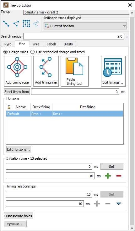
Creating an electronic tie-up
In an electronic tie-up, you can program the initiation timings and edit the detonator timings. To generate an electronic tie-up, there are three components which you need to define:
-
Timing horizons
A timing horizon is associated with hole intervals which define parts of the hole that need to have a specific timing for the tie-up. -
Hole timings for each horizon (usually through creating timing roses or lines)
Timing roses and timing lines provide you with a central control for adding timing to holes. You can associate holes with a timing rose or a timing line. Adjusting the timing rose or line will then automatically adjust the timings of each hole associated with it. -
Harness wire
In order to detonate explosives, electronic tie-ups need initiation systems. Initiation systems are added to the tie-up using the Wire tab. Harness wire is used to physically tie-up the electronic detonators so the initiation timings assigned to them can be programmed by a logger.
To create an electronic tie-up, follow these steps:
-
Select the desired blast in the view window or data explorer.
-
On the Charging ribbon, in the Design group, select
 Create Tie-up Design. Alternatively, right-click on a blast Tie-ups container in the data explorer and select
  New Tie-up Design... from the context menu.
The Tie-up Editor will appear. -
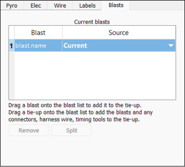
Select the Blasts tab.
-
Select the desired blast data source. To do this, follow these steps:
-
In the Current blasts table, select the Source column drop-down. BlastLogic will display the data sources available for the corresponding blast.
-
Select the desired source from the Source drop-down. The drop-down contains four types of sources:
-
Plan
Select the Plan option to create a tie-up using only charge plan data. In this case, no loaded or reconciled data is included in the tie-up. This option is in bold to signify that it is a special data type that you can only access in the tie-up editor and fly rock modelling tool. -
Current
Select the Current option to create a tie-up using reconciled data. If there is no reconciled data, BlastLogic will load the plan data instead (but not any loaded data). This option is in bold to signify that it is a special data type and not a snapshot. -
Reference design snapshot
The name of the reference design snapshot will appear as an option in the drop-down. For example, in the image below, the snapshot HP, is in bold to represent that it is the reference design snapshot. Select this option to create a tie-up using the reference design snapshot data.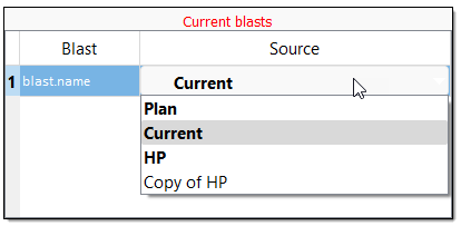
-
Other snapshots
Any other snapshots related to the blast will also appear in the drop-down. Select the name of the desired snapshot to create a tie-up using that snapshot’s data. These snapshots will not be in bold.
-
-
-
Select the Elec tab in the panel.
-
Optionally, edit the timing horizons. A timing horizon specifies how you wish to assign timings to an interval of a hole. To edit these, select Edit horizons... below the Horizons table. The Edit Horizons for <tie-up name> panel will appear.
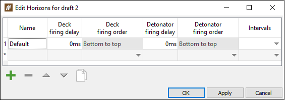
The Default horizon covers the entire length of the hole. No intervals are assigned to this horizon and therefore any parts of the hole that are not associated with an interval will appear in this default horizon. You can add horizons by clicking
 and entering the appropriate information into the table.
 Expand for more information on the edit horizons options
The table contains the following columns:
-
The Deck firing delay is the delay between multiple decks within a horizon.
-
The Detonator firing delay is the delay between multiple detonators within a deck.
-
The Detonator firing order is the order between multiple detonators within a deck.
The panel contains the following options:
-
To remove a timing horizon, select the horizon and click
 .
. -
To clone a timing horizon, select the horizon and click
 .
. -
To reorder the timing horizons, select the horizon you wish to move and click the
 and
and  arrows.
-
-
Add a timing tool. In BlastLogic there are two timing tools you can use to automatically assign initiation timings to holes:
-
Timing line
 Expand for more information on the timing line.
To create a timing line, follow these steps:
-
Select the desired horizon from the Horizons table in the Tie-up Editor.
-
Select the Add timing line tool from the Tie-up Editor.

The status bar will appear at the bottom of the view window.

-
Click the desired points in the view window to form the timing line. BlastLogic will connect the clicked points to display the timing line.
 Expand for an alternative selection method.
Alternatively, enter the initial desired point into the First point coordinate fields on the status bar and select
 to confirm the point. The First point label will change to Next point which allows you to enter the next line point. You can continue this process until you have entered all the desired timing line points.
-
Press Enter or click
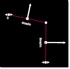
 to complete the timing line. A common timing line is V-shaped and points towards the holes, with a different burden relief on each side.
-
Adjust the timing line. You can use the following options to adjust the timing line:
-
To select a point on a timing line, ensure the
 Select points mode is selected in the data explorer toolbar.
 -
To adjust the burden relief of a timing line segment, drag the arrow for that segment using the middle mouse button.
-
To adjust the shape of the timing line, drag a point on the timing line using the middle mouse button.
-
To move the timing line, select all of the points on the timing line and drag one of the points using the middle mouse button. You can select all of the segments of the timing line by right-clicking on the timing line and selecting Select All Segments from the context menu.
-
To adjust the initiation time of the timing line, drag the arrows either to the left (to decrease) or right (to increase) using the middle mouse button.
-
To split a single timing line segment into two segments, right-click on the segment and select Split Segment from the context menu.
-
To delete a single timing line segment, right-click on the segment and select Delete Segment from the context menu.
-
To copy the timing line to another location, right-click on the timing line and select Copy Timing Line from the context menu.
-
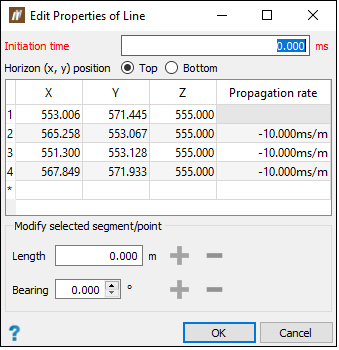
To view and edit the properties of a timing line, right-click on the line and select Edit Properties of Line... from the context menu. The Edit Properties of Line panel will appear.
-
To delete the timing line, right-click anywhere on the timing line and select Delete Timing Line from the context menu.
-
When drawing a timing line, BlastLogic will associate all holes without initiation times with the timing line. To associate only a selected number of holes to the timing line, select a set of holes, right-click on the timing line and select Associate with Selected Holes from the context menu. This tool can be useful when you add multiple timing lines and timing roses to a tie-up.
 Expand for more information on line initiation timings
A timing line has a variable number of edges each with a different burden relief value. The software determines which edge of the timing line the hole should be under the influence of and then uses the distance from edge to the hole to calculate its initiation time.
The distance calculations only consider the X and Y of the hole collars and of the timing line. Additionally, a fixed delay can also be added to the initiation times for holes associated with a timing line.
-
-
-
Timing rose
 Expand for more information on the timing rose.
To create a timing rose, follow these steps:
-
Select the desired horizon from the Horizons table in the Tie-up Editor.
-
Select the Add timing rose tool from the Tie-up Editor.

The status bar will appear at the bottom of the view window.

-
Click the point you wish to place the timing rose in the view window. BlastLogic will create an example timing rose centred at this point.
 Expand for an alternative selection method.
Alternatively, enter the initial desired point into the First point coordinate fields on the status bar and select
 to confirm the point. The First point label will change to Second point which allows you to enter the point you wish the timing rose to extend to.
 -
Click another point which sets the size of the timing rose. The further away you click from the first point, the larger the timing rose will be.
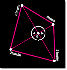
The timing rose is diamond shape with equal burden relief values for each of its four directions. The larger the timing rose, the larger the burden relief in ms/m is for each corner of the timing rose. You can alter the orientation of the rose to adjust the direction of the burden relief.
-
Adjust the timing rose. You can use the following options to adjust the timing rose:
-
To select a point on a timing rose, select the
 Select points in the data explorer toolbar.
 -
To adjust the shape of the timing rose, drag a point on the timing rose using the middle mouse button.
-
To move the timing rose, drag the point in the middle of the rose using the middle mouse button.
-
To copy the timing rose, right-click on the timing rose and select Copy Timing Rose from the context menu.
-
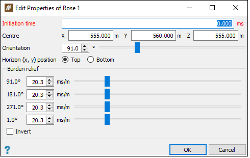
To view and edit the properties of a timing rose, right-click on the line and select Edit Properties of Rose... from the context menu. The Edit Properties of Rose panel will appear.
-
To adjust the initiation time of the timing rose, drag the centre arrows either to the left (to decrease) or right (to increase) using the middle mouse button.
-
To invert the timing rose, right-click on the timing rose and select Invert from the context menu.
-
To delete the timing rose, right-click anywhere on the timing rose and select Delete Timing Rose from the context menu.
-
When drawing a timing rose, BlastLogic will associate all holes without initiation times with the timing rose. To associate only a selected number of holes to the timing rose, select a set of holes, right-click on the timing rose and select Associate with Selected Holes from the context menu. This tool can be useful when you add multiple timing lines and timing roses to a tie-up.
 Expand for more information on rose initiation timings
A timing rose has four sides each with a different burden relief value. The initiations times for holes assigned to a timing rose are calculated based on the position of the hole from the timing rose and which side of the timing rose is closest to the hole. The distance between the hole and the timing rose and the corresponding burden relief for the closet side is then used to calculate the initiation time.
The distance calculations only consider the X and Y of the hole collars and of the timing rose. Additionally, a fixed delay can also be added to the initiation times for holes associated with a timing rose.
-
-
-
-
Add harness wire. To do this, follow these steps:
-
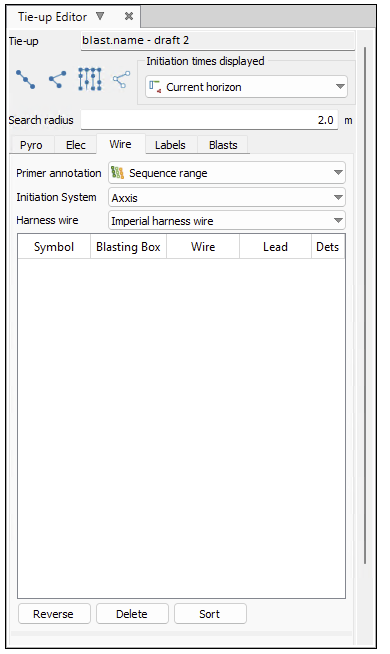
Select the Wire tab in the tie-up editor.
-
Select the desired attributes from the Primer annotation, Initiation System and Harness wire drop-downs.
Note:You can find a list of the available initiation system and harness wire products in the blast product catalogue. You can find this catalogue by selecting Blast Product Catalogue from the Setup group on the Home ribbon. For more information on this catalogue, see Blast product catalogue section of the Setup page.
 Expand for information on the DetNet - DigiShot initiation system.
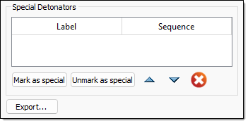
When using the DetNet - DigiShot initiation system, you can mark holes as special to indicate that they are considered out of sequence. You can use this special tag to mark either an ad hoc and (or) a re-drill hole. The special hole contains detonators that were not a part of the plan.
-
To mark holes as special, select the holes and click Mark as special.
-
To remove special status from selected holes, select the holes and click Mark as unspecial.
-
-
Select the desired connection mode.
 Expand for more information on the connection modes.
There are four connection modes to select from:
-
Row-by-row

The row-by-row mode ties up all holes inside the selected cursor range.
-
Hole-by-hole

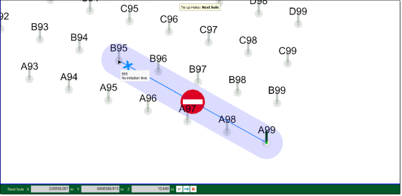
The hole-by-hole mode ties up a series of holes one-by-one.
If you attempt to connect two holes over a distance greater than the connector length, BlastLogic will prevent you from connecting the holes.
-
Auto-fill

The auto-fill mode automatically ties up rows or echelons across a control line template.
-
Dummy hole-by-hole

The dummy hole-by-hole mode ties up a series of hole one-by-one and creates dummy holes when you click in free space. Creating dummy holes allows for more flexibility when creating the shape of the tie-up.
Note:You can only connect harness wire using holes along a line
 or hole by hole
  . You cannot connect harness wire by automatically filling in echelons across a control line
  .
.
-
-
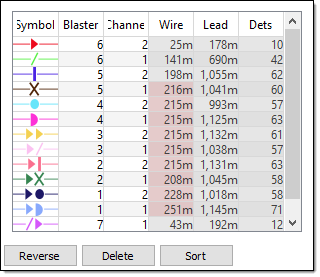
Connect the desired holes in the view window by selecting the holes in a sequential order. The connections will appear in the tab table.
 Expand for more information on connecting the wire
As you connect the wire between the holes in the view window, BlastLogic displays a line between the consecutively clicked holes. These lines have unique symbols and colours to represent each type of harness wire. You can view details of each connection in the editor table.
The limits for the maximum wire length, maximum lead length, and maximum detonator count per harness wire run are set as properties of the electronic initiation system in the Blast Product Catalogue. If a limit is exceeded, the cell in the harness wire table will be highlighted in red. Hover over the cell to see the tool tip error message.
-
Optionally, you can use the following options to adjust the connections:
-
-
To reverse the direction of a harness wire run, select the harness wire run in the table and click Reverse.
-
To delete a harness wire run, select the harness wire run in the table and click Delete.
-
To sort the harness wire runs in the table, click Sort.
Creating a pyrotechnic tie-up
A pyrotechnic tie-up uses surface connectors to physically connect detonators between holes in a blast.
To create a pyrotechnic tie-up, follow these steps:
-
Select the desired blast in the view window or data explorer.
-
On the Charging ribbon, in the Design group, select
 Create Tie-up Design. Alternatively, right-click on a blast Tie-ups container in the data explorer and select
  New Tie-up Design from the context menu.
The Tie-up Editor will appear.
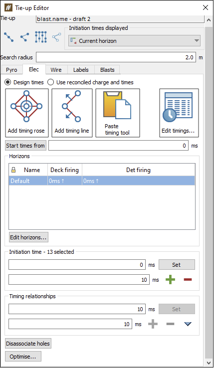
-
Select the Blasts tab.

-
Select the desired blast data source. To do this, follow these steps:
-
In the Current blasts table, select the Source column drop-down. BlastLogic will display the data sources available for the corresponding blast.
-
Select the desired source from the Source drop-down. The drop-down contains four types of sources:
-
Plan
Select the Plan option to create a tie-up using only charge plan data. In this case, no loaded or reconciled data is included in the tie-up. This option is in bold to signify that it is a special data type that you can only access in the Tie-up Editor and Fly Rock Modelling tool. -
Current
Select the Current option to create a tie-up using reconciled data. If there is no reconciled data, BlastLogic will load the plan data instead (but not any loaded data). This option is in bold to signify that it is a special data type and not a snapshot. -
Reference design snapshot
The name of the reference design snapshot will appear as an option in the drop-down. For example, in the image below, the snapshot HP, is in bold to represent that it is the reference design snapshot. Select this option to create a tie-up using the reference design snapshot data.
-
Other snapshots
Any other snapshots related to the blast will also appear in the drop-down. Select the name of the desired snapshot to create a tie-up using that snapshot’s data. These snapshots will not be in bold.
-
-
-
Select the Pyro tab in the panel.
-
Select the connectors you wish to use from the connector table.
Tip!You can add or edit existing connectors using the
 Blast Product Catalogue tool (Home ribbon > Setup group >
  Blast Product Catalogue). For more information on this catalogue, see Blast Product Catalogue.
 You can also edit or change the connectors by following the steps in the Pyro section.
-
Optionally, set the Line curve mode. BlastLogic allows you to make this selection solely to make each connector easier to see in the view window (for example, to prevent overlapping connectors).
-
Select the desired active connector from the table.
-
Select a tie-up connection mode button in the tie-up editor.
The tie-up holes status bar will appear.

 Expand for more information on the connection modes.
There are four connection modes to select from:
-
Row-by-row

The row-by-row mode ties up all holes inside the selected cursor range.
-
Hole-by-hole

The hole-by-hole mode ties up a series of holes one-by-one.
If you attempt to connect two holes over a distance greater than the connector length, BlastLogic will prevent you from connecting the holes.

-
Auto-fill

The auto-fill mode automatically ties up rows or echelons across a control line template.
-
Dummy hole-by-hole

The dummy hole-by-hole mode ties up a series of hole one-by-one and creates dummy holes when you click in free space. Creating dummy holes allows for more flexibility when creating the shape of the tie-up.
-
-
Select each hole you wish to connect, according to the selected connection mode.
-
Press Enter or double-click the last hole to end a sequence of connectors. This allows you to restart a new sequence that is not connected to the previous sequence without closing and re-opening the status bar.
Tip!You can change the connector type and connection mode at any time without closing the status bar with the following methods:
-
To use a different connector type, simply click the desired type in the editor table and continue connecting holes in the view.
-
To change the connection mode, simply click the desired mode in the editor and continue connecting holes in the view. Alternatively, use the following keyboard shortcuts to change between the connection modes:
Connection Mode Keyboard Shortcut Row-by-row 
Q Hole-by-hole 
W Auto-fill 
E Hole by hole with dummies 
R
-
-
Press Esc or click
 after connecting the desired holes.
 -
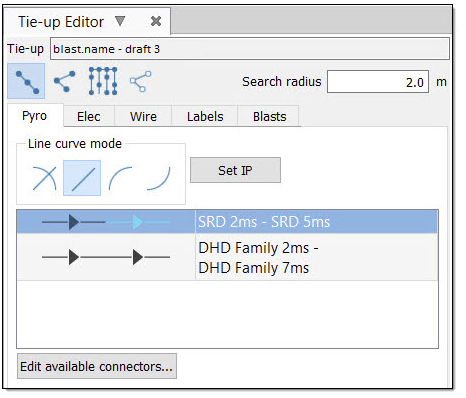
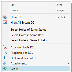
Set an initiation point. You can use either of the following methods to set the initiation points:
-
Select Set IP in the tie-up editor and click the desired hole in the view window.
-
Right-click on the desired hole in the view window and select
 Set IP from the context menu.
-


If connectors are present in the tie-up, then after you set this point, BlastLogic will calculate and display the delay times for the tie-up.

BlastLogic signifies the initiation point with a red pentagon near the hole. To change the initiation point, repeat these steps using a different hole.
Publishing a tie-up
BlastLogic allows you to publish tie-ups as the following types:
-
Draft
You can create a draft tie-up to form initial plans or experiment with different designs. This is the default state of tie-ups when they are first created. You can publish multiple draft tie-ups to share and edit amongst your team. -
Design
A design tie-up is the tie-up design you intend to perform and can be thought of as the tie-up plan. -
Actual
You can create an actual tie-up after the tie-up has been completed. In an actual tie-up, you can record and publish any changes made in the actual tie-up process. This allows you to analyse the differences between the design and actual tie-ups.
To publish the tie-up, follow these steps:
-
Right click on the tie-up in the Tie-ups folder of the desired blast, in the data explorer. A context menu will appear.
-
Hover over the Publish option on the context menu. A side context menu will appear.
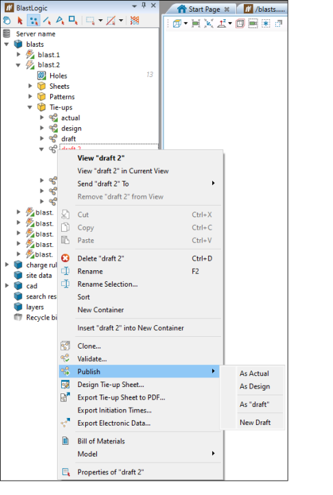
-
Select the desired publishing option. The following options are available:
-
As Actual or As Design
Selecting one of these options creates an actual or a design tie-up for your blast. If have already published an actual or a design tie-up for the corresponding blast, selecting one of these options will overwrite the respective tie-up.
Note: If a draft has been published as an Actual tie-up, it can be later published only as a Design tie-up, and vice versa. Changing the published tie-up to Actual or Design will overwrite the existing tie-up of the respective type.
After selecting either of these options, the Publish draft of <blast name> panel will appear. This panel displays a list of any issues with the blast or tie-up that you must address before publishing the tie-up. The panel has the following functionality:
-
The icon indicates the severity of the issue.
-
For certain issues, BlastLogic will provide a button in the Action column, which you can click to aid you in fixing the issue. Otherwise, you will have to navigate to the issue area and solve the problem.
-
When publishing a tie-up as an actual tie-up, you must record the time when the tie-up was completed in the Completed time drop-down.
 Note:
Note:If the draft you are trying to publish has already been published as a design or actual tie-up, BlastLogic will display the following message in the panel.

To fix this, clone the draft by selecting Clone. BlastLogic will automatically change the selected tie-up to the cloned version, allowing you to make any edits and publish the clone as the desired type.
-
-
As "draft"
This option is visible when there is an unpublished draft in your
 Tie-ups container.
 For example, if there is an unpublished tie-up named draft 2 and a published draft tie-up, the following dialog window will appear:
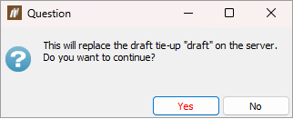
When you click Yes, the tie-up that has previously been published as draft will be overwritten.
-
New Draft
Creates a new draft tie-up.
For example, if there is a published tie-up named draft and an unpublished tie-up named draft 2, when you choose to publish the draft 2 as a New Draft, it will be published as draft 2, and the existing published tie-up named draft will not be overwritten by draft 2.
-
Exporting an electronic tie-up
To export an electronic tie-up, follow these steps:
-
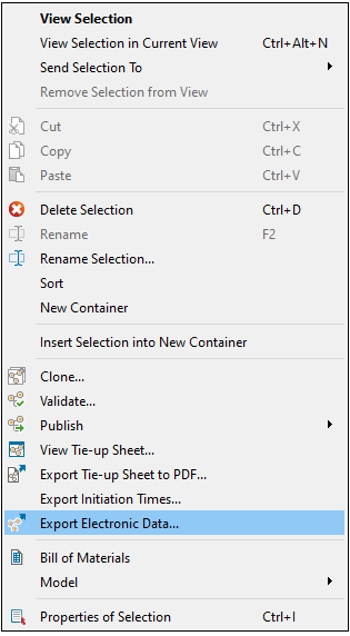
Right click on a tie-up and select Export electronic data....
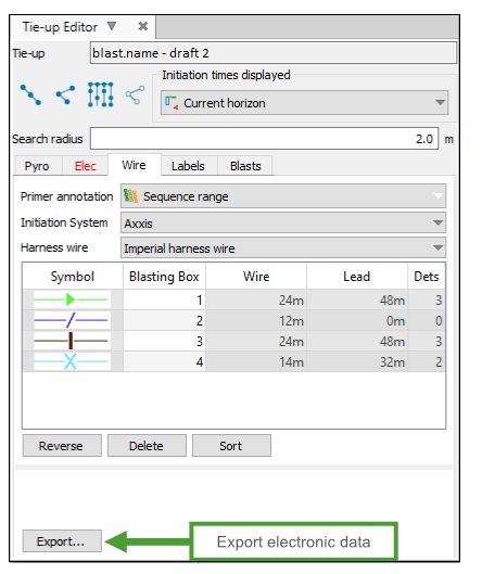
Another way is to click the Export button on the tie-up editors Wire tab.
- Choose the Logger.
-
Choose the format to export to. All electronic initiation systems provide the option of exporting in PDF format. Various electronic initiation systems provide different formats where the electronic data can be exported to. For example, the DetNet - DigiShot initiation system can export the electronic data to a tagger report.
-
Any issues with the tie-up will be shown at the bottom of the panel. Any issues with icon must be fixed before the electronic data can be exported.
-
Click OK.
Exporting AXXIS electronic data
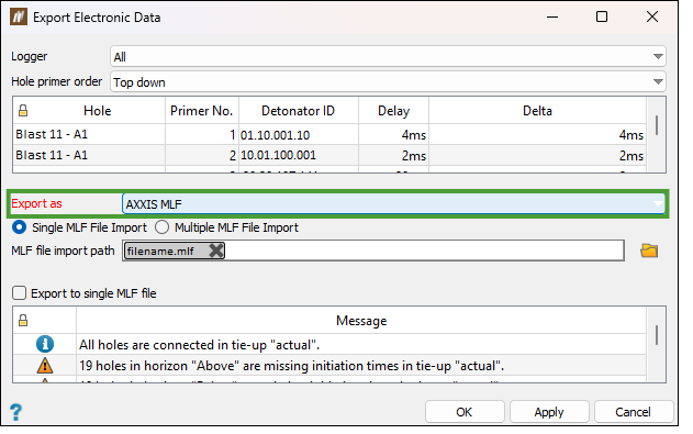
AXXIS export requires importing the MLF file from the logger that corresponds to the tie-up that is being exported. BlastLogic uses this imported MLF file to create a new MLF file with added timings and validation to be sent back to the logger.
When Export electronic data is selected on an AXXIS tie-up, actual electronic timings have to be imported via an MLF file.
Follow these steps to import an MLF file and export electronic data:
-
Click the
 button on the MLF file import path. You can choose to import a single or multiple MLF files at once.
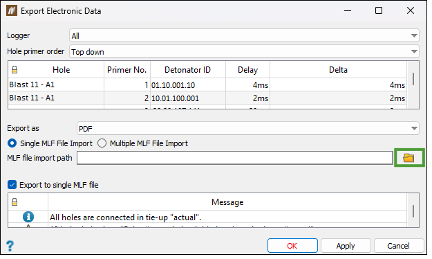
Note: After importing an MLF file, the table will list the detonator ID from the MLF file next to its corresponding detonator.
-
Select AXXIS MLF from the Export as drop-down list.
-
Check the validation list for any message errors in the tie up and click OK.
Note: You have to resolve the errors before exporting the file.
Exporting initiation times
To export an electronic tie-up’s initiation times, follow these steps:
-
Right-click on a tie-up and select Export Initiation Times....
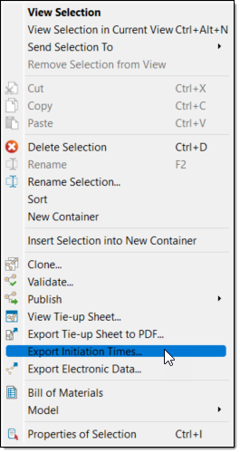
The Export Initiation Times panel will appear.

-
In the Export data to field, specify the location you wish to save the export to. You can either type the location path into the field or select
 to browse to the location in the file explorer.
 -
Click OK or Apply.
Using the Tie-up Editor
The Tie-up Editor has the following tabs:
Pyro
The main use of the Pyro tab is to create a pyrotechnic tie-up design. To do this, see the Creating a Pyrotechnic Tie-up page.
You can also use this tab in the following ways:
Adding and editing the available pyrotechnic connectors
In BlastLogic, you can set the available connectors for a given tie-up. This is useful when narrowing down the total list of available connectors to just those that you will use for the tie-up design. To do this, follow these steps:
-
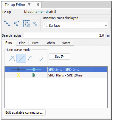
Select the Pyro tab in the Tie-up Editor.
-
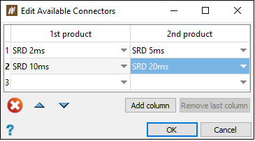
Select Edit available connectors.... The Edit Available Connectors panel will appear. The table displays connector products that are available in the tie-up design.
In this panel, you can complete the following tasks:
-
To create a connector, select the product you wish to use from the appropriate cell drop-down.
-
To create a composite connector with two products, add a product using the drop-down in the 2nd product column. Use the Add product column button to create composite connectors with more than two products. For example, to create a composite connector with four products, click the Add product column button twice and then choose the desired products.
-
To delete a connector, select it and click
 .
. -
To remove a product from a connector, select it and press Del.
-
The order of products in the table is the order they will appear in the connector list in the tie-up editor. To re-order the products, select the products you wish to move. Move the products up by clicking
 or down by clicking
  .
. -
You can move one or more products to the very top of the list by selecting the products and clicking
 . This is useful for placing the connector products that you will commonly use at the top of the list.
-
- Click OK. The additions or edits are now available in the tie-up editor table.
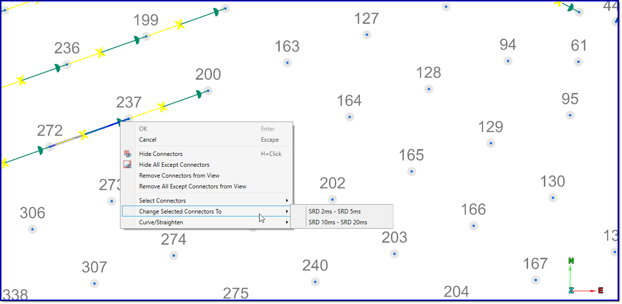
Changing the pyrotechnic connectors
In BlastLogic, you can change the product for selected connectors. To do this, follow these steps:
-
Select the connectors you wish to change in the view window. To select the connectors, set the selection mode to
 Select edges.
Note: The connectors can also be selected by right-clicking on a connector and choosing the connector product from the Select Connectors drop-down list.
Tip! You can also select a group of connectors by right-clicking on a connector and selecting. -
Right-click on one of the selected connectors and choose the connector to change to from the Change Selected Connectors To drop-down list. The connectors will be changed and the delay times will be automatically recalculated, if the initiation point is set.
Elec
You can perform the following tasks in this tab:
- Editing timings
- Editing the initiation times for selected holes
- Editing the selected timing relationships
- Disassociating the timing relationships from central control
- Optimising the tie-up timings
- Using reconciled charge and times
Editing timings
The design timing information for the holes in an electronic tie-up can be modified in a table by clicking the Edit timings button.

The Edit timings panel shows the initiation time for each hole, and the delay from the preceding hole or associated timing. The delay between explosive decks and the delay between detonators can also be adjusted on a hole by hole basis.
To view the timing information for a tie-up with multiple horizons, select the horizon to view from the Horizon drop-down list.
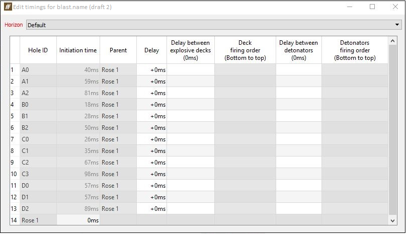
Note: Values that are greyed out are not editable.
Editing the initiation times for selected holes
-
Select the holes to change the initiation times for.
Note: The selection mode needs to be either in
 (objects) or
  (points) selection mode.
-
Enter the initiation time and then click the Set button.
-
To adjust the initiation times by a set amount, set the amount in ms to adjust the initiation time by and then use the
 or
or  buttons.
 -
To adjust the initiation times in the view window middle-click drag on one of the arrows. Dragging to the right increases the initiation times. Dragging to the left decreases the initiation times.
Editing the selected timing relationships
-
Select the timing connections to change the timing relationships.
Note: The selection mode needs to be in the
 (edges) selection mode.
-
Enter the timing delay and click the Set button.
-
To adjust the outgoing delays by a set amount, set the amount in ms to adjust the timing relationship by and then use the
 or
or  buttons. All of the subsequent connected holes initiation times will be adjusted accordingly.
 -
To adjust the timing relationships in the view window, middle-click drag on one of the arrows.
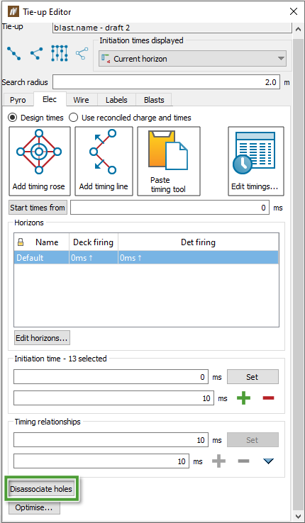
Disassociating the timing relationships from central control
-
Select the holes to remove the timing relationships from.
Note: The selection mode needs to be either in
 (objects) or
  (points) selection mode.
 -
Click Disassociate holes. The initiation times of the holes will remain unchanged, but if you open the Edit timings panel, you will find that the timings of the hole are no longer connected to the central control (the timing rose or timing line).
Optimising the tie-up timings
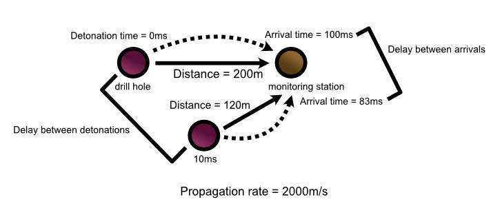
This tab also provides an optimisation tool for electronic tie-ups that adjusts initiation times in order to reduce the number of detonations occurring per timing envelope window to an acceptable level.
Only an unpublished tie-up can be optimised.
To optimise tie-up timings for a blast:
-
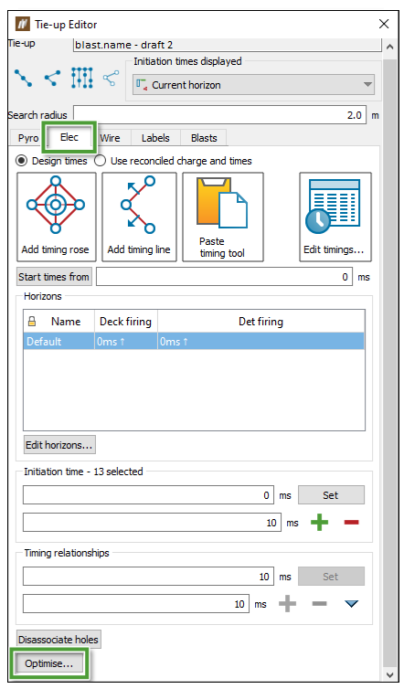
On the Elec tab click the Optimise... button.
-
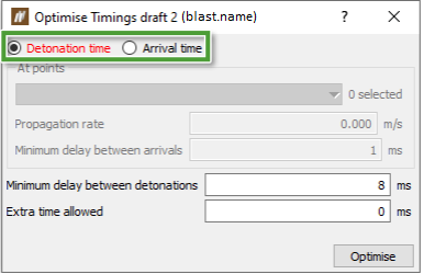
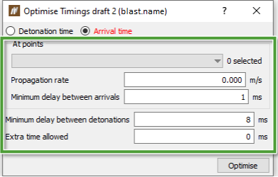
Timings can be optimised based on detonation time or arrival time at specified locations. Select one option.
-
If the arrival time method is selected in step 2, set the propagation rate, the minimum delay between arrivals and detonations, and extra time allowed. Select locations at which to calculate timings. The tool will attempt to adjust the initiation times such that every detonation and arrival is separated by at least the entered values.
-
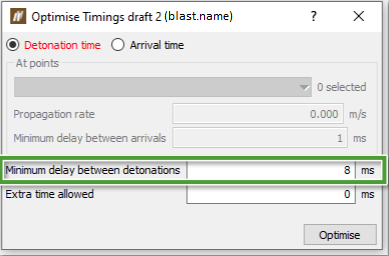
If the detonation time option is selected, specify the Minimum delay between detonations. The tool will attempt to adjust the initiation times such that every detonation is separated by at least this value from the immediately preceding and following detonations.
-
Click Optimise.
-
Inspect the result using the Timing Envelope and (or) Timing Contour tools.
Using reconciled charge and times
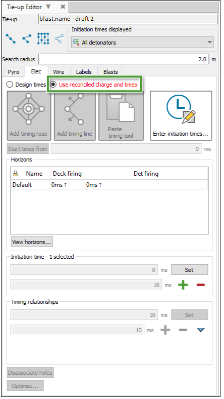
The Elec tab provides you with the option to use reconciled charge and times on a tie-up. After creating a design tie-up and assigning these times in the field, you can use this option to create a tie-up based on these actual times. An advantage of this is that you can apply BlastLogic‘s modelling tools to a tie-up with reconciled charge and times, so you can model the actual detonator times.
Note: Selecting this option will also override the charge data source to reconciled decks only.
To use the reconciled charge and times option, follow these steps:
-
On the Elec tab, select the Use reconciled charge and times radio button. BlastLogic automatically sets the Initiation times displayed field to All detonators and greys out all of the tab options, except Enter initiation times... and View horizons....
-
Enter the actual initiation timings from the field. Click Enter initiation times to bring up the Initiation Time Data Entry panel. For steps on entering data into this panel, see Initiation Time Data Entry. If you have already entered the initiation times, ignore this step.
BlastLogic will add the entered times to the corresponding holes in the view window.
-
Optionally, view the tie-up horizons by selecting View horizons.... The Horizons for <tie-up name> panel will appear, displaying the horizons of the tie-up.
Wire
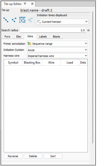
The Wire tab allows you to connect harness wire in your tie-up design. You can use harness wire along the surface of a blast to connect electronic detonators to a logger.
To connect harness wire in the tie-up, follow these steps:
-
Select the Wire tab in the tie-up editor.
-
Select the desired attributes from the Primer annotation, Initiation System and Harness wire drop-downs.
Note:You can find a list of the available initiation system and harness wire products in the blast product catalogue. You can find this catalogue by selecting
 Blast Product Catalogue (Home ribbon > Setup group). For more information on this catalogue, see Blast Product Catalogue section of the Setup topic.
 Expand for information on the DetNet - DigiShot initiation system
When using the DetNet - DigiShot initiation system, you can mark holes as special to indicate that they are considered out of sequence. You can use this special tag to mark either an ad hoc and (or) a re-drill hole. The special hole contains detonators that were not a part of the plan.
To mark holes as special, select the holes and click Mark as special.
To remove special status from selected holes, select the holes and click Unmark as special.

-
Select the desired connection mode.
 Expand for more information on the connection modes.
There are four connection modes to select from:
-
Row-by-row

The row-by-row mode ties up all holes inside the selected cursor range.
-
Hole-by-hole

The hole-by-hole mode ties up a series of holes one-by-one.
If you attempt to connect two holes over a distance greater than the connector length, BlastLogic will prevent you from connecting the holes.

-
Auto-fill

The auto-fill mode automatically ties up rows or echelons across a control line template.
-
Dummy hole-by-hole

The dummy hole-by-hole mode ties up a series of hole one-by-one and creates dummy holes when you click in free space. Creating dummy holes allows for more flexibility when creating the shape of the tie-up.
Note:You can only connect harness wire using holes along a line (
 ) or hole by hole (
 ). You cannot connect harness wire by automatically filling in echelons across a control line (
 ).
).
-
-
Connect the desired holes in the view window by selecting the holes in a sequential order. The connections will appear in the tab table.

 Expand for more information on connecting the wire
As you connect the wire between the holes in the view window, BlastLogic displays a line between the consecutively clicked holes. These lines have unique symbols and colours to represent each type of harness wire. You can view details of each connection in the editor table.
The limits for the maximum wire length, maximum lead length, and maximum detonator count per harness wire run are set as properties of the electronic initiation system in the blast product catalogue. If a limit is exceeded, the cell in the harness wire table will be highlighted red. Hover over the cell to see the tool tip error message.
-
Optionally, use the following options to adjust the connections:
-
To reverse the direction of a harness wire run, select the harness wire run in the table and click Reverse.
-
To delete a harness wire run, select the harness wire run in the table and click Delete.
-
To sort the harness wire runs in the table, click Sort.
Labels
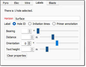
The Labels tab allows you to customise the hole labels in the view window. To do this, follow these steps:
-
Select the Labels tab in the Tie-up Editor.
-
Select the desired holes in the view window.
-
Select the desired hole horizon from the Horizon drop-down.
-
Select the desired radio button option in the Label section.
-
Edit the desired label properties using the corresponding value fields or sliders.
Blasts
The Blasts tab displays the current blasts in the editor and their associated source data. You can use this tab in the following ways:
Selecting a blast data source
BlastLogic allows you to select the data source you wish to use when creating a tie-up for a blast.
To specify the tie-up data source, follow these steps:
-
Select the Blasts tab in the tie-up editor.

-
In the Current blasts table, select the Source column drop-down. BlastLogic will display the data sources available for the corresponding blast.
-
Select the desired source from the Source drop-down. The drop-down contains four types of sources:
-
Plan
Select the Plan option to create a tie-up using only charge plan data. In this case, no loaded or reconciled data is included in the tie-up. This option is in bold to signify that it is a special data type that you can only access in the tie-up editor and fly rock modelling tool. -
Current
Select the Current option to create a tie-up using reconciled data. If there is no reconciled data, BlastLogic will load the plan data instead (but not any loaded data). This option is in bold to signify that it is a special data type and not a snapshot. -
Reference design snapshot
The name of the reference design snapshot will appear as an option in the drop-down. For example, in the image below, the snapshot HP, is in bold to represent that it is the reference design snapshot. Select this option to create a tie-up using the reference design snapshot data.
-
Other snapshots
Any other snapshots related to the blast will also appear in the drop-down. Select the name of the desired snapshot to create a tie-up using that snapshot’s data. These snapshots will not be in bold.
-
Adding blasts to a tie-up
-
Select the Blasts tab in the tie-up editor.
-
Select the blast you wish to add in the data explorer.
-
Drag the blast from the data explorer into the in the Blasts tab table using the middle mouse button.
Note: Other tie-up objects can also be dragged and dropped into the table using the middle mouse button.
Removing blasts from a tie-up.
-
Select the Blasts tab in the tie-up editor.
-
Select the blast that you wish to remove from the table.
-
Click Remove.
Splitting blasts from a tie-up
-
Select the Blasts tab in the tie-up editor.
-
Select the blast that is to be split from the table.
-
Click Split. The split tie-up will appear in the data explorer under the Tie-up container for the selected blast.
