Material Flow
Source file: 2.material-flow-subtab-new.htm
The ![]() Material Flow subtab is used to define the overall material process flow from the source to the final product output from the processing facility. To enter it, go to the
Material Flow subtab is used to define the overall material process flow from the source to the final product output from the processing facility. To enter it, go to the ![]() Process Setup tab and select
Process Setup tab and select ![]() Material Flow from the drop-down list.
Material Flow from the drop-down list.
Material Flow components
The following components can be added in the ![]() Material Flow tab:
Material Flow tab:
| Pit | Represents the in situ resource to be mined. See Pit Models for more information. |
| Crusher | Equipment used to initially break up the mined material. The crusher receives ore from the pit models and sends it to one or more standard processes. A single pit can feed one or more crushers, and a crusher can feed one or more standard processes. For details, see Crusher and Standard Process. |
| Standard Process | A generalised process used for further material refinement. Standard processes represent ore processing streams within mills. These can be fed by crushers and stockpiles, but not directly from a pit. Standard processes represent the final destination of any ore, and therefore cannot be used to feed another process. Revenue for the operation is determined based on the product produced by processes. For details, see Crusher and Standard Process. |
| Initial Stockpile |
An existing stockpile for single element setups that represents stockpiles of ore that have material on them prior to the start of the schedule. Initial stockpiles can be used together with manual and process stockpiles. They can be reclaimed from, but cannot be added to during the schedule. See Stockpiles for more information. Note: The added initial stockpile will be displayed as Stockpile in your setup. |
| Manual Stockpile | Gives you greater control over grade ranges by allowing for the stockpiling of ore so that it can be reclaimed at a later date, either to meet mill capacity or for blending purposes. See Stockpiles for more information. |
| Beneficiation Group | A more detailed representation of a particular type of mill. It contains various subprocesses that sort ore into product streams with uplifted grades and reject streams that can be sent to waste, or stockpiled for further processing. A beneficiation group has its own crusher, so can be fed directly from a pit or stockpile. It can be used in conjunction with standard processes. For more information, see Beneficiation Group. |
| Waste Dump | Used as a final destination for waste material mined from pits. See Waste Dump for more information |
To schedule you need to add to your flowchart, at minimum, a pit to mine from and one of the following component sets:
-
A crusher and process to produce a saleable product from ore mined from the pit.
Or
-
A beneficiation group to produce a saleable product from ore mined from the pit.
By the end of the schedule, all pits and stockpiles will be fully depleted.
Material Flow toolbar
The Material Flow toolbar allows you to add and remove process nodes included in your setup, and to customise the way they are displayed in the flowchart.

|
|
Auto layout diagram Aligns components of your model to visualise precedence and dependencies between the nodes. To align the components in your model, click this button on the toolbar. The components will be aligned according to their precedence and dependencies between them. |
|
|
Size diagram to fit Places your diagram in the centre of your workspace (viewing window). |
|
|
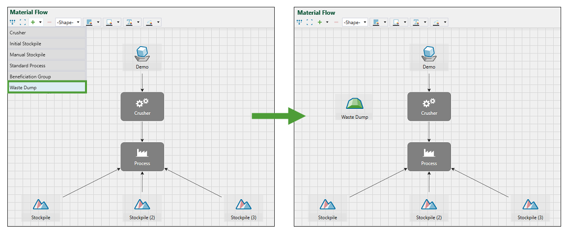
Add node Allows you to add a new process node to your setup. You can select from the following components:
For more information, see Material Flow components and the topics dedicated to each component (Crusher and Standard Process, Stockpiles, Beneficiation Group, and Waste Dump). To add a node to your setup, click the
See Configuration for more information on setting up each process node of the flowchart. |
|
|
Delete selected object Deletes the selected component from your setup. Tip: You can also delete a component by selecting it and pressing Delete. |
|
|
Allows you to change the shape of the selected process node. Note: Only Crusher and Process can have their shape changed. To change the shape of a process node:
The shape you selected will be applied to the selected process node. 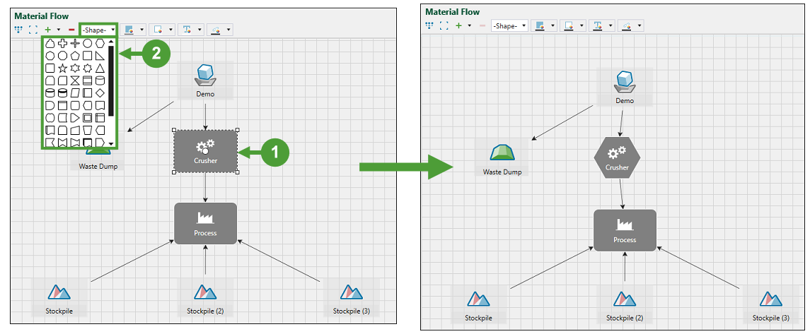 |
|
|
Allows you to change the colour of the selected process node. Note: Only Crusher and Process can have their colour changed in the flowchart. To change the colour of a process node:
The colour you selected will be applied to the selected process node. 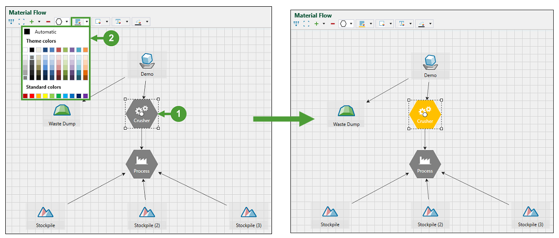 |
|
|
Allows you to change the colour of the shape outline of the selected process node. Note: Only Crusher and Process can have the colour of their shape outline changed in the flowchart. To change the colour of the shape outline of a process node:
The colour you selected will be applied to the selected process node. 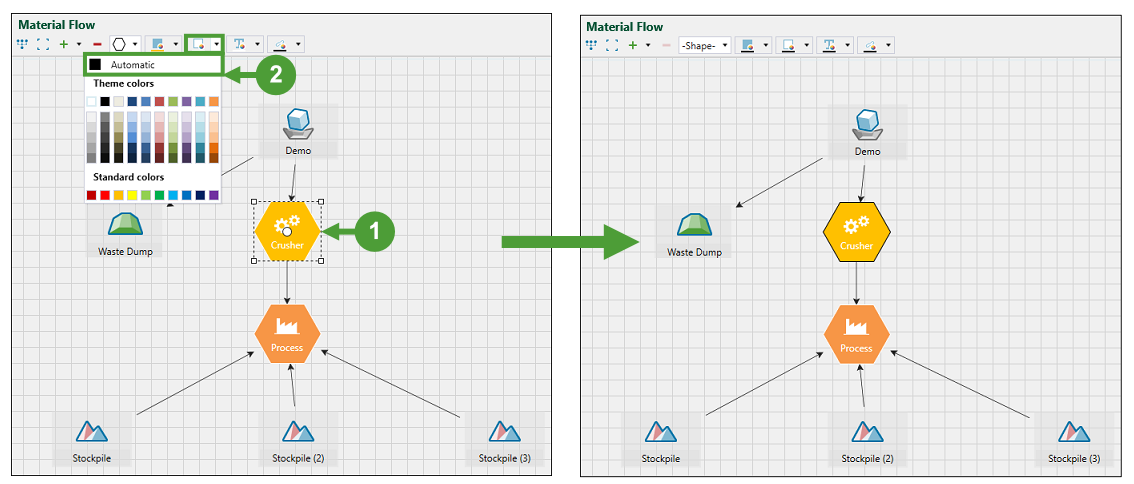 |
|
|
Allows you to change the text colour of the selected process node. Note: Only Crusher and Process can have their text colour changed in the flowchart. To change the text colour of a process node:
The text colour you selected will be applied to the process node. 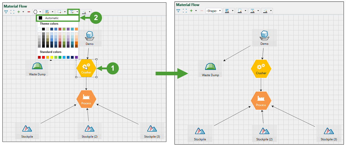 |
|
|
Allows you to change the colour of arrows that link the process nodes. To change the colour of the linking arrow:
|

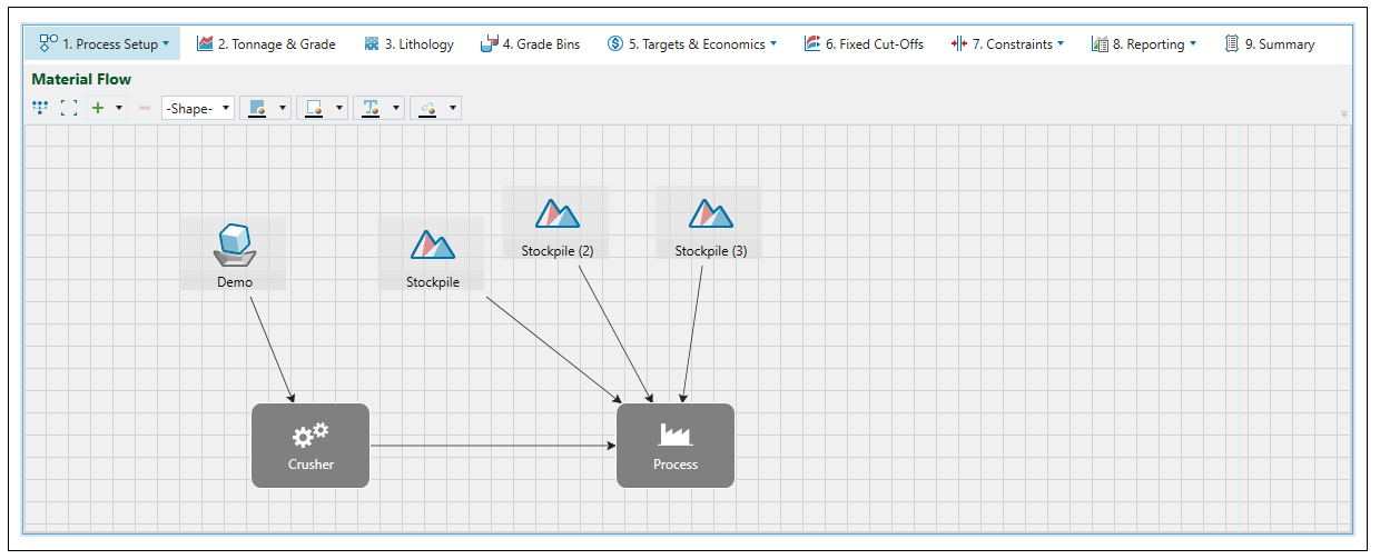
Linking process nodes
Linking two process nodes together defines precedence and dependency between them. Creating a net of interconnections between all process nodes in the setup establishes the process flow in Evolution.
Follow these steps to link two process nodes together:
-
Click on the process node to which you want to assign a dependent process.
-
Click on the white circle that has appeared.
-
Drag the arrow all the way to the circle on the component that you want to be the dependent one.
-
Release the mouse. The dependency will be created.
Note: The arrowhead always points to the dependant node.

Renaming process nodes
You can set a custom name for each process node in your setup. You can do so either on the ![]() Material Flow or
Material Flow or ![]() Configuration subtab.
Configuration subtab.
-
To set a custom name in the flowchart of the
 Material Flow subtab, double-click on the selected component in the flowchart, and enter a new name in the editable text field.
Press Enter or click outside the process node that is currently being edited to apply the new name.
-
To set a custom name in the
 Configuration subtab, click on the process and enter a new name in the Name field.
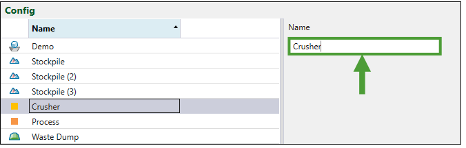
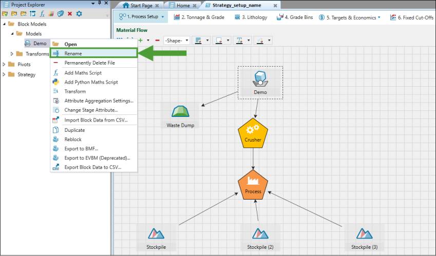
Note: The two methods mentioned above do not allow changing the name of the model (pit). To change the name of the pit in your setup, click on it in the project explorer, select Rename and enter the new name in the editable text field.