Equipment
The ![]() Equipment tab is used to specify the type of equipment used in the mining process, its parameters, and operation characteristics. This tab is composed of the following subtabs:
Equipment tab is used to specify the type of equipment used in the mining process, its parameters, and operation characteristics. This tab is composed of the following subtabs:
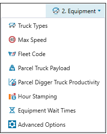
 Truck Types
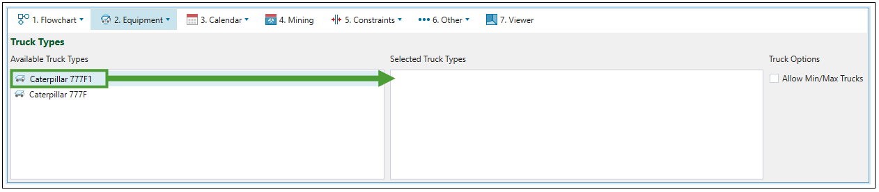
Use the ![]() Truck Types subtab to add truck types defined in your project to your setup. To configure a new truck for the project, see Creating Trucks.
Truck Types subtab to add truck types defined in your project to your setup. To configure a new truck for the project, see Creating Trucks.
To add a previously configured truck type to your setup, drag it from the Available Truck types column to the Selected Truck Types column.
After selecting the required truck types, go to the ![]() Calendar >
Calendar > ![]() Equipment subtab and set the number of trucks to meet the target for the total mass of material moved at the end of each period. Material extraction will be ordered to use only the configured number of trucks.
Equipment subtab and set the number of trucks to meet the target for the total mass of material moved at the end of each period. Material extraction will be ordered to use only the configured number of trucks.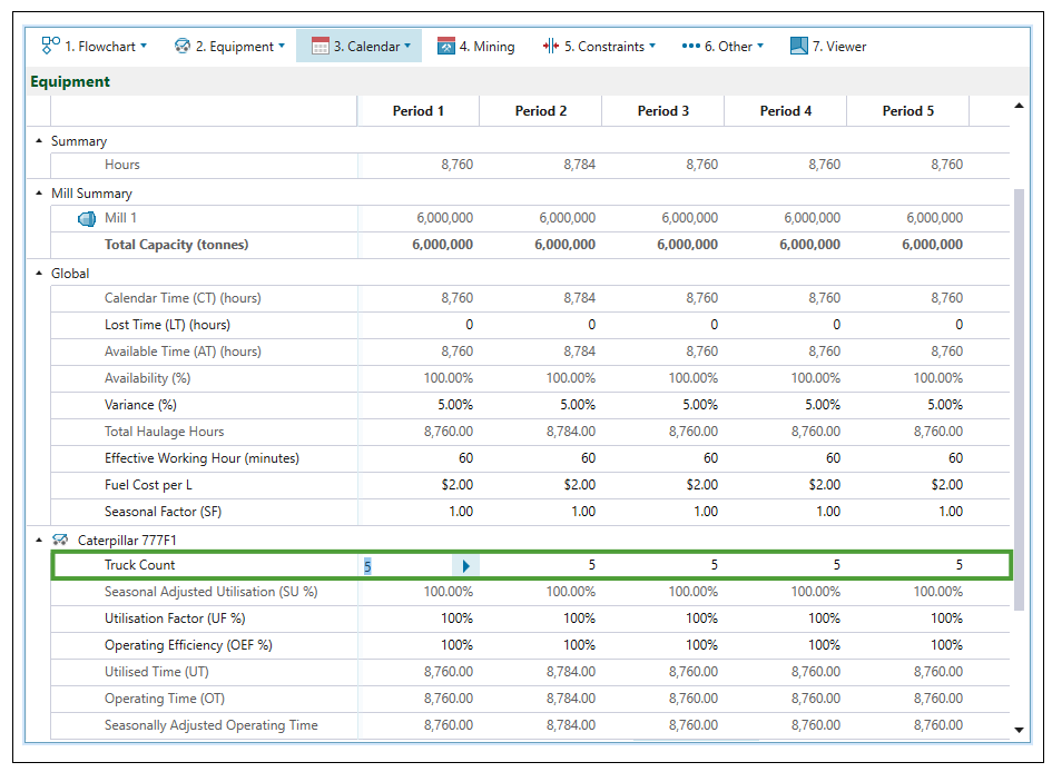
The Allow Min/Max Trucks checkbox in the ![]() Truck Types subtab allows you to set the number of the trucks used in each period more flexibly. After checking it, the fields for setting the maximum and minimum truck count in each period will appear in the
Truck Types subtab allows you to set the number of the trucks used in each period more flexibly. After checking it, the fields for setting the maximum and minimum truck count in each period will appear in the ![]() Calendar >
Calendar > ![]() Equipment subtab.
Equipment subtab. 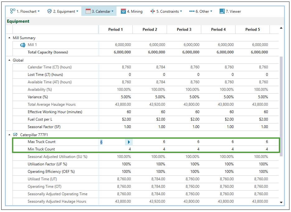
 Max Speed
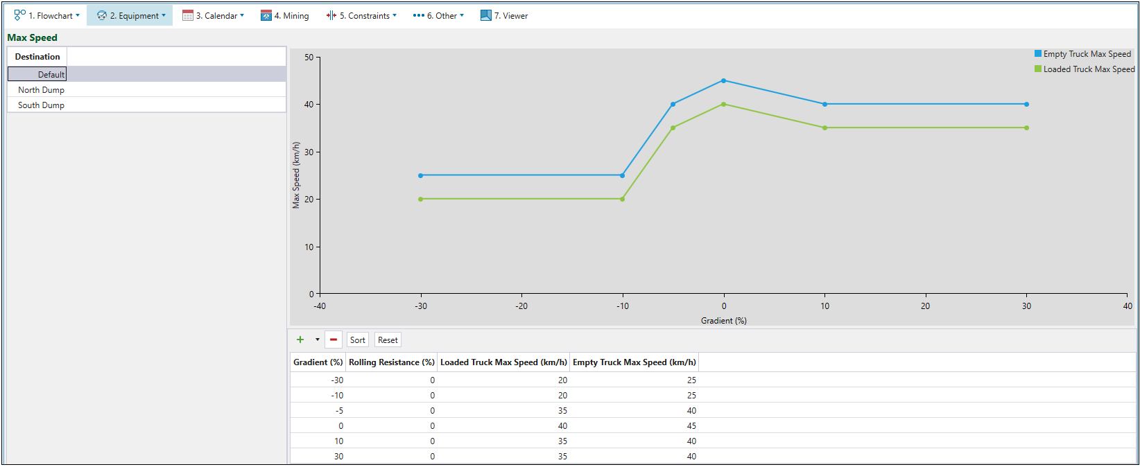
The ![]() Max Speed subtab is used to plot the unloaded and loaded maximum truck speeds against the road gradient. All points in the graph are editable. Values from the graph will be used to calculate travel time when the setup contains a road network.
Max Speed subtab is used to plot the unloaded and loaded maximum truck speeds against the road gradient. All points in the graph are editable. Values from the graph will be used to calculate travel time when the setup contains a road network.
To edit the maximum speed:
-
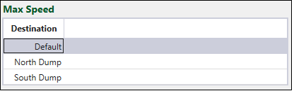
Select a destination. The list of destinations is based on the locations specified in the flowchart of your setup. The Default option allows you to set the maximum speed for all non-destination travel (such as in-pit and surface roads).
Note: The applied speed is the lowest of the Maximum Speed tab (either by selected destination or Default), or the edge maximum speed.
Note: The maximum speed may be also applicable to each vertex or point. This will specify the maximum speed at which a truck can be travelling when it passes through that point (the speed that is equal to zero means that there is a stop sign). As a result of having to stop or slow down at the vertex, the truck may be unable to reach the maximum speed that the edge and Maximum Speed tab limits would normally dictate.
-
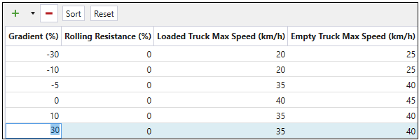
Edit table cells to reflect the road conditions in the setup.
-
Press
 to add a new row to the speed curve in the table.
 -
Press
 and select the required number to add multiple rows at once.
-
Press
 to remove the currently selected row from the table.
 -
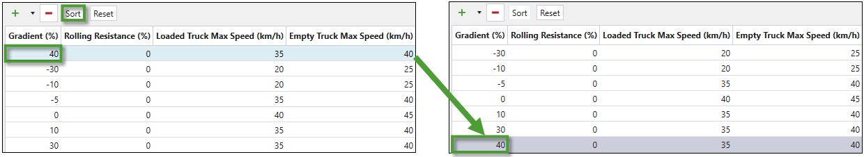
Press Sort to arrange the rows in the table in the Gradient(%) ascending order.
-
Press Reset to revert the changes that you have made in the table.
-
- The applied changes will be reflected in the graph.
 Fleet Code
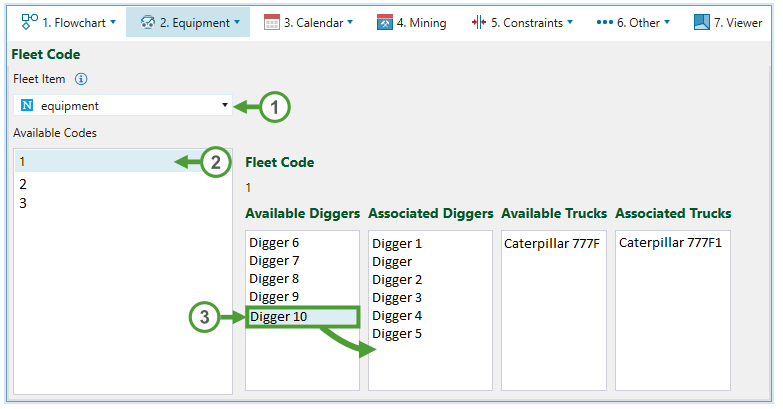
This is an integer code in the model which allows you to map available diggers and trucks to particular fleets, stages, and lithologies.
Follow these steps to assign the available equipment to the selected fleet:
-
Select an item from the Fleet Item drop-down menu.
-
From the Available Codes column, select the fleet code for which you would like to make the assignment.
-
Drag the required diggers or trucks from the corresponding Available columns to the Associated columns.
 Parcel Truck Payload
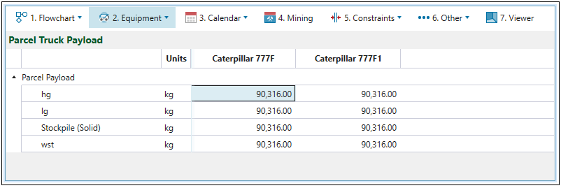
The ![]() Parcel Truck Payload subtab allows you to assign the maximum mass a truck can carry in a single trip per parcel.
Parcel Truck Payload subtab allows you to assign the maximum mass a truck can carry in a single trip per parcel.
 Parcel Digger Truck Productivity
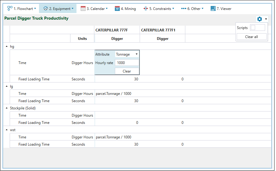
The Parcel Digger Truck Productivity subtab is used to set the mining duration per parcel for each digger-truck combination. You can choose to either enter a rate which is converted to a duration or use scripting by enabling the scripting slider under the ![]() Settings in the top right corner.
Settings in the top right corner.
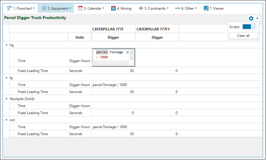
| The screen when scripts are disabled | The screen when scripts are enabled |
|
|
The productivity that results from the script above is 1h/1000t of hg material.
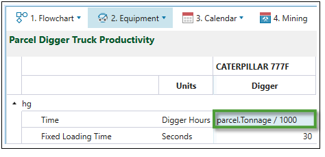
Based on the script used in the above example, the productivity of the Caterpillar 777F digger is 1000 tonnes per hour.
Once a schedule is created, the results can be checked using pivot reporting. See Pivot Reporting for more information.
 Hour Stamping
Origin allows you to set the period in which each solid is mined based on its value for the selected attribute. Optionally, the extraction order of each solid can be controlled by selecting an attribute for Rank.
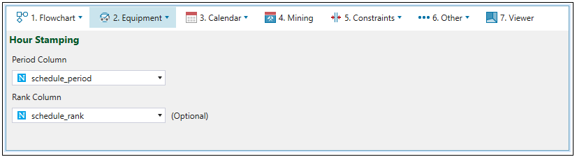
For more information on the stamping period and rank back to the model from an existing schedule, see Stamp Period and Rank Back to Model.
 Equipment Wait Times
Equipment wait times are time frames required for the equipment to be set up.
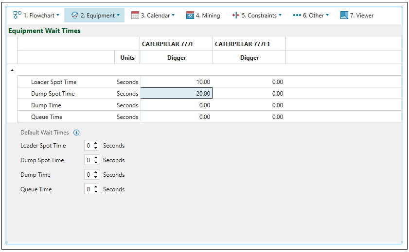
Note: If a particular wait time is not set for a digger-truck combo, the corresponding default wait time will be used instead (a wait time is considered not set if its value is 0).
| Loader spot time | Time for a truck to position itself under the digger. |
| Dump spot time | Time for a truck to position itself so that it can dump material. |
| Dump time | The time it takes to dump material in a waste dump (typically 30 seconds). |
| Queue time | The time it takes for a truck to wait for other trucks which are already dumping or being loaded. |
 Advanced Options
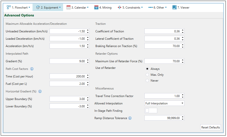
The ![]() Advanced Options subtab allows you to define the following parameters for haulage-based schedules.
Advanced Options subtab allows you to define the following parameters for haulage-based schedules.
Maximum Allowable Acceleration/Deceleration
| Unloaded Deceleration (km/h/s) | Limits the deceleration of an empty truck to the specified number. This will override the retard curve when necessary. |
| Loaded Deceleration (km/h/s) | Limits the deceleration of a loaded truck to the specified number. This will override the retard curve when necessary. |
| Acceleration (km/h/s) | Limits the maximum acceleration of a truck. This will override the rimpull curve when necessary. |
Interpolated Path
| Gradient (%) | Sets the gradient that should be used when a path is interpolated. |
Path Cost Factors
These options allow you to compare the available paths a truck could take to a given destination. Setting them is irrelevant to any actual costs that are reported out by the schedule, and also does not impact the net present value. These factors are also used to sequence the waste utilities.
Note: When the sequence of waste utilities is specified, the cells with the lowest waste cost should be filled first.
| Time (Cost per Hour) | Assigns the cost per hour (path time cost per hour). |
| Fuel (Cost per L) | Assigns the cost per litre of fuel used (path fuel cost per litre). |
Horizontal Gradient (%)
Horizontal gradient is specified to define if a road segment is classified as uphill, horizontal, or downhill.
| Upper Boundary (%) | Specifies the maximum inclination of the road network. |
| Lower Boundary (%) | Specifies the maximum declination of the road network. |
Traction
| Coefficient of Traction | Specifies the friction between truck tyres and ground. |
| Lateral Coefficient of Traction | Determines the proportion of the rimpull curve that can be successfully used to accelerate while turning. |
| Braking reliance on Traction (%) | Proportionally increases the distance required for braking (represents reliance on traction coefficient to slow truck down). |
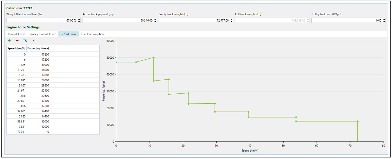
Retarder Options
| Maximum Use of Retarder Force (%) | This setting helps to prevent overheating of the retarder on long steep descents. The lower this number, the slower the truck will move when retarder is in use. |
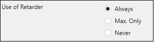
| Use of Retarder |
Each truck has a retard curve, which can be confirmed when double-clicking on the corresponding truck in the project explorer. It determines how much braking force the truck can exert based on its current speed. The retarder provides the engine a way to determine the braking force of a truck. Its usage can be set to Always, Max. Only, or Never by the radio buttons provided.
|
Miscellaneous
| Travel Time Correction Factor | This factor can be used to account for any additional factors impacting travel time. It multiplies the travel time (without including delays) that has been previously calculated based on other parameters. |
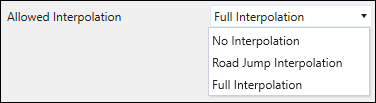
| Allowed Interpolation |
You can set the following types of interpolation from the drop-down menu:
|
| In-Stage Path Finding |
Usually, in the case of path finding from a ramp to a solid on a bench, a path is calculated inside the solids or blocks that constitute the shape of the bench. However, when this option is enabled, the path is calculated inside the solids or blocks that share both a stage and a bench. |
| Ramp Distance Tolerance | This setting defines the maximum allowed distance to provide a truck access from a haulage network edge to a given solid. |
Calendar
The following is a table of calculated fields in the Calendar > Equipment subtab.
| Field | Equation |
| Calendar Time (CT) |  |
| Lost Time (LT) | You provide this value. |
| Available Time (AT) |

|
| Availability (%) |

|
| Utilisation Factor (UF) | You provide this value. |
| Utilised Time (UT) |

|
| Utilisation |

|
| Operating Efficiency (OEF) | You provide this value. |
| Effective Utilisation (EU) |

|
| Total Haulage Hours (THH) |

|
| Seasonality Factor (SF) | You provide this value. |
| Seasonally Adjusted Haulage Hours (SHH) |

|
| Seasonally Adjusted Utilisation (SU) |

|
| Operating Time (OT) |

|
| Seasonally Adjusted Operating Time (SOT) |

|
