View Manager
Source file: epoch-setups-viewer-view-manager.htm
Use the View Manager in conjunction with the viewer to display objects such as models and road networks. In addition to hiding or displaying objects, you can also inspect and highlight your data by using the dedicated tools.
 Dynamic Colour
To add a dynamic colour to a single model or multiple models, complete the following steps:
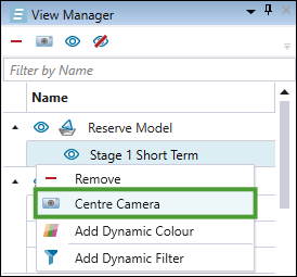
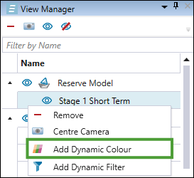
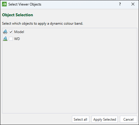
- Right-click the model in the View Manager to open the context menu and select Add Dynamic Colour.
- Select the models to apply the dynamic colour from the panel and click Apply Selected.
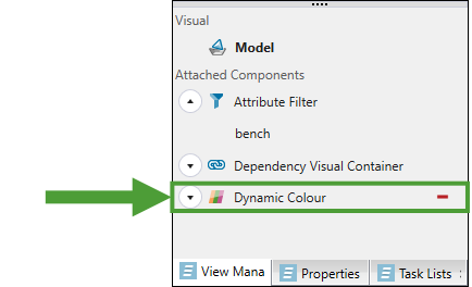
- Expand the Dynamic Colour panel.
- Select an attribute from the drop-down to apply the colour.
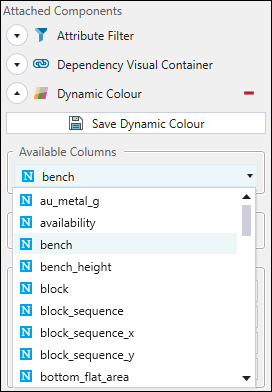
- Select a predetermined colour scheme. The model will be coloured based on its values for the attribute you have selected from the drop-down.
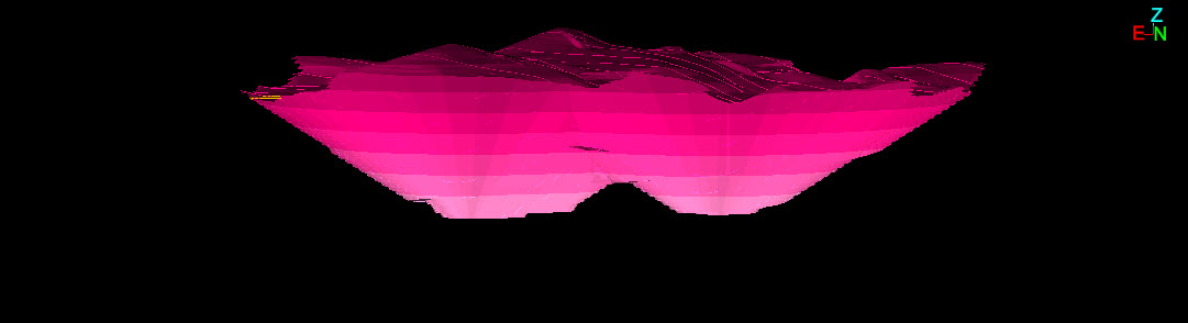
The following image is an example of a pit with a dynamic colour applied according to the pit bench value.
You can save the dynamic colour scheme you have created by clicking the
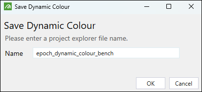
The colour scheme will be saved in the project explorer.
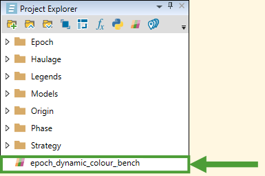
To edit the saved dynamic colour scheme, double-click it in the project explorer and make the required changes.
To change the name of the saved dynamic colour scheme, right-click it in the project explorer and click
 Rename.
To apply the saved dynamic colour scheme to other models, drag it from the project explorer to the model that you have open in the viewer.
For more information on applying colour bands, see Add Colour Bands.
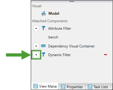
 Dynamic Filter
Applying filters in the viewer allows you to inspect values and attributes within particular solids in your model.
Follow these steps to add a dynamic filter to your model:
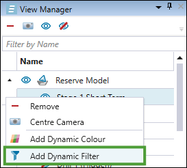
- Right-click the model in the View Manager to open the context menu and select Add Dynamic Filter.
- In the Select Viewer Objects window, select the models to which you wish to apply the dynamic filter and click Apply Selected.
- Expand the Dynamic Filter panel in the View Manager on the right side of your screen.
- From the
 drop-down menu, select the type of filter that you wish to add.
 -
== (Equality)
-
!= (Not equal to)
-
> (Greater than)
-
< (Less than)
-
> = (Greater than or equal to)
-
< = (Less than or equal to)
-
== (Equal to)
-
!= (Not equal to)
-
Starts with
-
Ends with
-
Contains
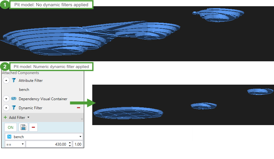
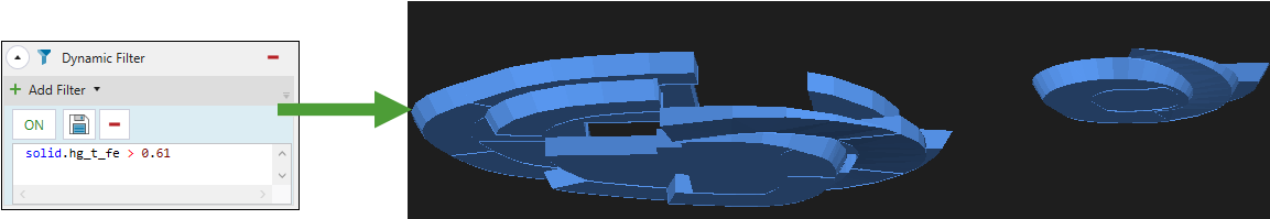
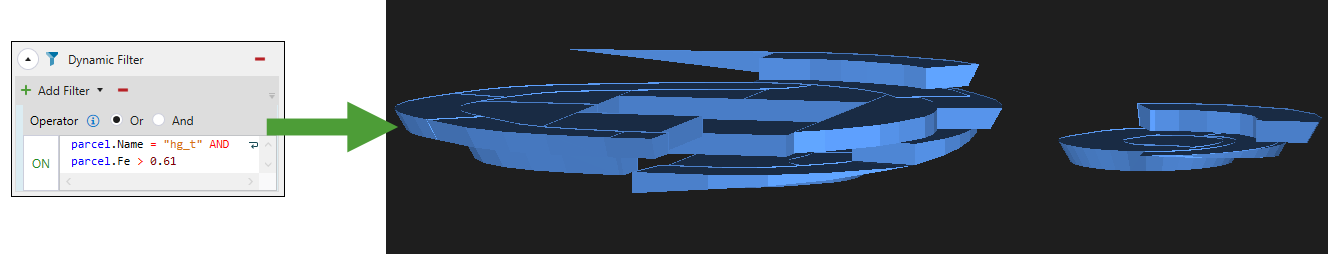
You can apply the following filter types:
| Numeric |
Allows you to customise the view of your model by applying a numeric value from the drop-down. In the example below, the model was filtered by applying bench
|
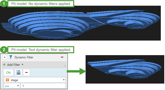
| Text |
Allows you to customise the view of your model by applying a text value from the drop-down. In the example below, the model was filtered by applying stage
|
| Solid script |
Allows you to filter the view of your model by applying a solid-related script.
|
| Parcel script |
Allows you to filter the view of your model by creating scripts at a parcel level.
For more information on creating parcels in the setup, see Parcel Reporting. |
-
Toggle the
 and
and  button to enable or disable the selected dynamic filter in your viewer.
 -
Click
 (Save Dynamic Filter) button to save the given filter. Next, enter the desired name in the Save Dynamic Filter panel. The colour scheme will be saved in the project explorer.
 Note: Parcel script filters cannot be saved.
-
To edit the saved dynamic filter, double-click it in the project explorer and make the required changes.
-
To change the name of the saved dynamic filter, right-click it in the project explorer and click
Rename. -
To apply the saved dynamic filter to other models, drag it from the project explorer to the model that you have open in the viewer.
-
Click
 (Delete the selected filter) to remove the dynamic filter from your setup.
 Centre Camera
To regain focus on a model in the viewer, right-click the model in the View Manager and select ![]() Centre Camera.
Centre Camera.