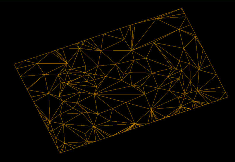
Surface
The following table describes the tools in the Surface section of the Edit tab.
| Tool | Description |
| Fix Surface | Fix self-intersections and inconsistent normals. |
| Despike | Removes spikes from a triangulation. |
| Simplify triangulation by facet count | Reduces the triangulation facet count, with no surface deviation limitation. |
| Simplify triangulation by distance error | Reduces the triangulation facet count, with a specified surface deviation limitation. |
| Combination Surface | Merges selected triangulation surfaces into a single surface |
| Fragment | Fragments a triangulation surface into multiple surfaces. |
| Offset Surface | Creates a solid around the selected surface. |
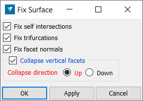
Fix Surface
To use the Fix Surface tool:
-
Select the surface you want to repair
-
Go to Edit > Surface > Fix Surface. This will open a new panel.
-
Optionally, check the Fix self intersections checkbox. This will:
-
Find intersecting facets in the surface and delete: This emulates the user querying the surface intersections in order to manually locate and delete triangles.
-
Fill holes on boundary edges: This emulates the user running the fill holes option. Note that this has logic to handle pits vs. closed solids such that the pit boundary edge is not considered a hole to be filled.
-
Orient the facet normals as consistently as possible after the changes to the surface.
-
-
Optionally, check the Fix trifurcations checkbox. This will:
-
Classify the facets by connectivity stopping at trifurcation boundaries: It then considers the surface areas of each group of connected facets and removes those considered insignificant. This is based on being less than 5% of the total surface area of the surface. The idea here is to get rid of tiny facets or groups of facets sticking off the side of the surface. These are sometimes quite hard to locate due to being internal to the overall solid result of a boolean operation.
-
Leave any trickier to handle trifurcation boundaries that cannot be fixed automatically. For example, consider a Möbius strip or Klein bottle where there is not really a way an algorithm can handle such a surface.
-
-
Optionally, check the Fix facet normals checkbox if you want to ensure that all facets are oriented in a consistent direction. You can check that this function has worked by using the Single Sided colouring function.
-
Optionally, check the Collapse vertical facets checkbox. This will remove vertical facets and close the hole this produces by moving the points along the bottom of the vertical region up or the points along the top down, adding points as necessary to neighbouring non-vertical facets to maintain a consistent surface.
-
Click OK or Apply.
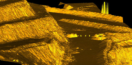
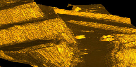
Despike
The Despike option removes spikes caused by dust or vegetation that may appear when creating a data model.
To remove spikes from a triangulation:
-
Select the triangulation to despike.
-
Go to Edit > Surface > Despike.
If unwanted points remain after running the despike tool, these must be manually deleted.
To manually despike a triangulation:
-
Select facet selection mode.
-
Manually draw clipping boxes around problem triangles (hold the SHIFT key down to select multiple areas).
-
Once the problem facets have been highlighted, press the DELETE key and they will be removed.
-
Right-click the surface to open a context menu and select Edit > Fill holes to fill the holes that remain. This will repair any holes present in the model.
The example below shows a data model before and after the despike function.
|
|
| Before | After |
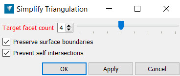
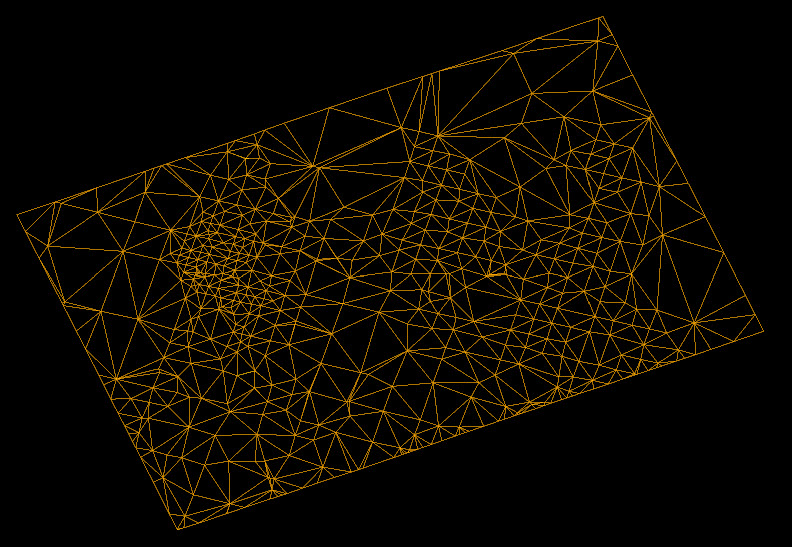
Simplify triangulation by facet count
The By Facet Count option allows triangulations to have their facet count reduced, while retaining the overall shape. This option works on a selection of facets that can be an entire triangulation, a group of triangulations or a selection of facet primitives on a triangulation.
To use this tool:
-
Go to Edit > Surface > By Facet Count. This will open a new panel.
-
Set the Target facet count. The Target facet count is the number of facets the simplified triangulation will contain.
The slider can be adjusted from one to the total number of triangles in the selection. If the slider is set to halfway, it will reduce the facet count by half. This can be applied repeatedly to further reduce the facet count by half each time this function is applied.
The simplification process will amalgamate the triangles in flat regions first, preserving edges and other curved areas. It will also simplify triangles around the boundary of the triangle selection.
-
Check the Preserve surface boundaries checkbox to leave the boundary unchanged.
-
Check the Prevent self intersections checkbox to stop the generation of intersecting facets.
You can also reduce the number of facets to a quarter of the original total by right-clicking the surface and selecting Edit > Simplify facets to 25%.
|
|
| Before | After |
Triangulation simplification can introduce inconsistencies in the surface, such as triangles that overlap or cross. To read more about how to check the validity of surface, click here.
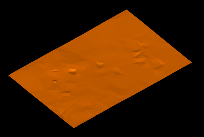
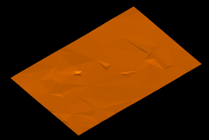
Simplify triangulation by distance error
The Simplify triangulation option allows triangulations to have their facet count reduced while retaining the overall shape. This option works on a selection of facets that can be an entire triangulation, a group of triangulations or a selection of facet primitives on a triangulation.
To simplify a triangulation by an allowable distance error:
-
Go to Edit > Surface > By Distance Error. This will open a new panel.
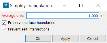
-
Enter the maximum allowable Average error by which the simplified surface can deviate from the original surface.
The Average error is the average distance from the original surface, thus there will be some areas of the new surface that are further away from the original surface than the average error.
The simplification process will amalgamate the triangles in flat regions first, preserving edges and other curved areas. It will also simplify triangles around the boundary of the triangle selection.
-
Check the Preserve surface boundaries checkbox to leave the boundary unchanged.
-
Check the Prevent self intersections checkbox to stop the generation of intersecting facets.
-
Click OK or Apply.
|
|
| Before | After |
Triangulation simplification can introduce inconsistencies in the surface, such as triangles that overlap or cross. To read more about how to check the validity of surface, click here.
Triangulation simplification can introduce inconsistencies in the surface, such as triangles that overlap or cross. To read more about how to check the validity of surface, click here.
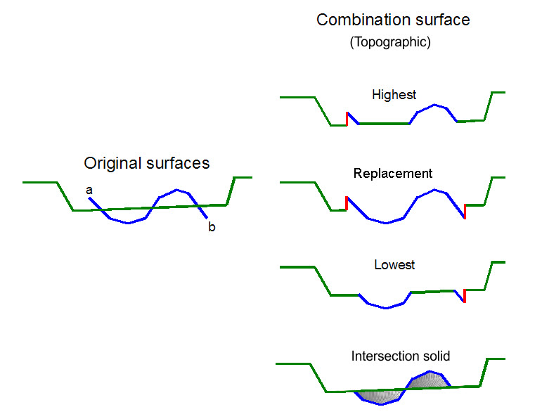
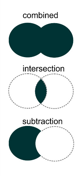
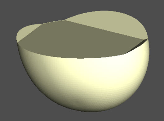
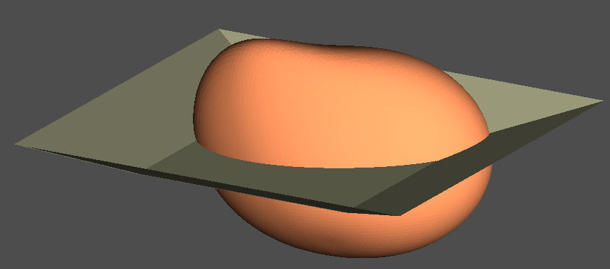
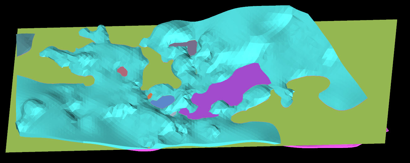
Combination Surface
The Combination Surface tool is used to merge selected triangulation surfaces Surface icon into one single surface (Lowest, Highest and Replacement), or closed solid (Intersection solid, Combined solid, Difference solid) . This may be useful when updating a data model and the region to be updated is fully enclosed by the existing data.
This option works best when one surface covers a larger area extent than the others in the selection.
To apply the tool:
-
Go to Edit > Surface > Combination Surface. This will open a new panel.
-
Select a surface type from the following options:
-
Topographic — Operates on topographic surfaces, allowing new surfaces or closed solids to be created based on different ways of combining the original surfaces.
-
Closed solid — Operates on closed solids (or volumes), allowing new closed solids to be created based on different ways of combining the original closed solids.
-
Solid and topography — Enables a solid triangulation to be clipped with a surface triangulation.
-
-
Select a combination type from the drop down list options. This will depend on the surface type you choose in step 2.
If you chose Topographic, the following options would be available:
-
Lowest — Combines the lowest parts of all surfaces.
-
Replacement — Replaces parts of the largest surface with smaller surfaces.
-
Highest — Combines the highest parts of all surfaces.
-
Intersection solid — Creates a closed solid between the highest and lowest points of the two intersecting surfaces.
If you set the Surface type to Closed solid, the following options are available:
-
Combined solid — Combines the original closed solids (volumes) into one closed solid (volume) enclosing all original closed solids (volumes).
-
Solid intersection — Creates a new closed solid (volume) where the original closed solids (volumes) overlap.
-
Solid subtraction — Creates a new closed solid (volume) where the first object has any overlap with a second object removed from it's shape.
If you chose Solid and Topography in step 2, the following options are available:
-
Keep solid above — Select this option if you want to keep the top portion of the solid.
-
Keep solid below — Select this option if you want to keep the bottom portion of the solid.
-
Keep solid above and below — Select this option if you want to keep the top and the bottom portions of the solid.
Keep solid above Keep solid below Keep solid above and below -
-
Check the Collapse vertical facets checkbox if you want to remove vertical facets and close the hole this produces by moving the points along the bottom of the vertical region up or the points along the top down, adding points as necessary to neighbouring non-vertical facets to maintain a consistent surface.
-
Click OK or Apply.
Fragment
Fragment is used to break up one or more triangulation surfaces where intersections exist with other surfaces.
-
Select at least two intersecting surfaces to be fragmented.
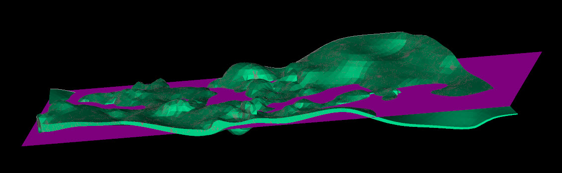
-
Go to Edit > Surface > Fragment.
-
For each fragmented surface, a new panel will appear. The panel will prompt you to store the
xlargest fragments as separate objects. Enterxand click OK. If you enter a value x which is less than the total fragments produced, you can choose to keep the remainder fragments by checking the Keep remainder fragments checkbox. The fragments will be stored under a remainder container.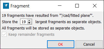
The selected surface(s) become fragmented and the original object is replaced by a container of the fragments.
Offset Surface
Offset Surface is used to create a closed triangulation around the selected object. This new triangulation is offset from the original by a nominated distance. Offset surfaces can be created around the following:
-
points
-
lines
-
polygons
-
ribbons
-
edge networks
-
stereonet blind zone / great circle / set window / grid / contours
-
drillholes
-
downhole geophysical logs
-
triangulations
To create an offset surface:
-
Select the required object
-
Go to Edit > Surface > Offset surface. This will open a new panel.
-
Nominate the Offset distance, level of Surface detail and the container you want to save the new surface in (Offset surface).
-
Click OK or Apply to save the surface to the surface container.
|
|
| Before | After |