Setting up a scan job
Before you can acquire scans, you need to configure the physical setup parameters of the scan job. You can do this from the  Setup tab.
There are three basic setup types to choose from, as follows:
-
Defined Name. A defined name scan job allows you to take scans from an unsurveyed location without any backsights. The physical setup could be on a tripod or a vehicle mount. Maptek Drive scans also use the defined name setup. The bearing can be supplied either from the internal compass, or derived from a vehicle’s GPS track. The position is supplied either by the scanner’s internal GPS or an external Bluetooth GPS. The filename of a defined name scan is based on a name supplied by the user. See Setting up a defined name scan job for details.
-
Survey Job. A survey job scan allows you to scan from a surveyed location such as over a survey mark or using a survey bollard. The surveyed location can either be set from a survey job file, set to the GPS position, or manually entered. The bearing is typically obtained by backsighting to another surveyed location, but the compass or vehicle GPS track can also be used if necessary. The filename of a survey job scan is based on the survey job name and the scanner location. See Setting up a survey job for details.
-
Multiple Backsights. A multiple backsights scan job uses multiple backsights to establish the scanner’s position and bearing rather than GPS information. The typical use case is when scanning underground. See Setting up a survey job with multiple backsights for details.
Setting up a defined name scan job
This section will guide you through the process of setting up a defined name scan.
Defined name scan setup types
Defined name scans are set up according to three different scanner and accessory applications. These are summarised below:
-
Using compass and GPS: High-precision GPS determines the scanner’s location and the onboard compass provides a rudimentary bearing. Additional bearing accuracy is required using in-field registration by registering in PointStudio.
-
Vehicle mount using GPS track: This type of scan is taken with a vehicle-mounted scanner. The vehicle is driven a short distance to determine a bearing prior to scanning.
-
Using Maptek Drive: Position and bearing information are continuously updated using Maptek Drive’s GPS and INS system. When connected to Maptek Drive, the Defined Name panel automatically switches to Drive configuration.
Setting up a defined name scan using compass or GPS track
To set up a defined name scan:
-
In the
Setup tab, tap Defined Name. -
Set a scan name.
-
Tap the button next to Scan name to show a list of previously used names.
-
Tap
 to add a new name to the list. The currently selected name will be used as the initial basis.
 -
Select a name and tap OK to set it.
-
-
Select the Heading to use as follows:
-
Compass: Use the scanner’s internal compass to set the heading.
Important: If scanning from a vehicle, make sure the
 Vehicle compass calibration toggle is enabled to apply the calibration factor.
 -
GPS track: The vehicle’s GPS track will be used to define the scanner heading.
TipTo obtain a heading from the vehicle’s GPS track, drive in a straight line for 5 to 10 metres. The heading is determined by sampling multiple positions as the vehicle moves. For the best results, follow these recommendations:
-
Avoid driving over uneven surfaces.
-
Minimise any variations in the track heading.
-
Avoid letting the vehicle roll back when coming to a stop.
-
-
Setting up a survey job
To set up a survey job, go to Setup >  Survey Job.
|
|
|
Figure 7-17 Survey job setup |
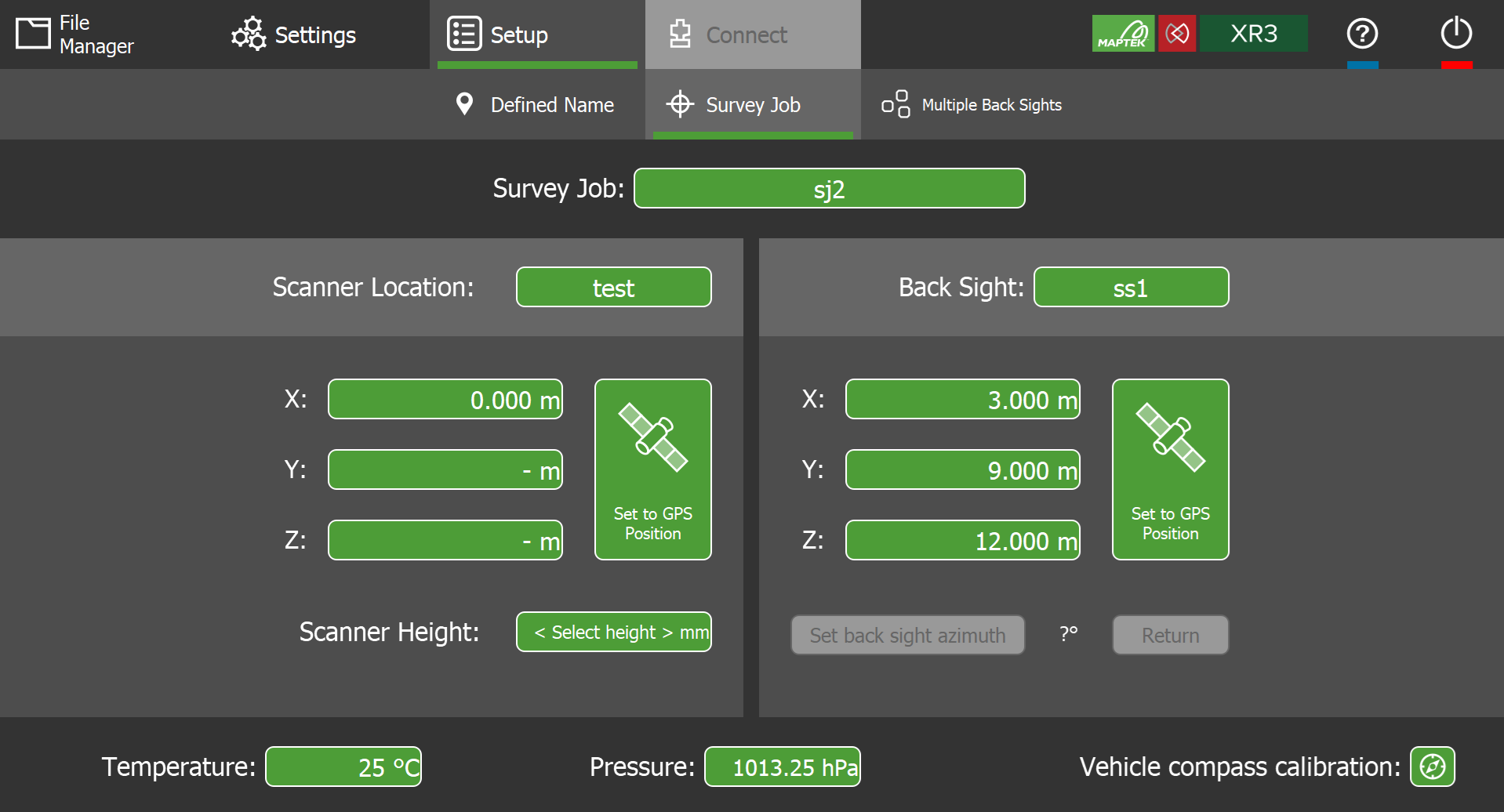
This setup type requires you to define the scanner location (e.g. from a survey station location or GPS location) and then establish the scanner bearing through the use of a backsight location. You can also use this panel to define the survey locations in your survey job database.
Configure the fields as follows.
Survey Job
Select the name of the survey job.
Each survey job corresponds to a database of survey station locations stored as a text file (.txt). Tap the button to display a list of existing survey job files stored in FieldHHC.
|
|
|
Figure 7-18 Survey job selection panel |
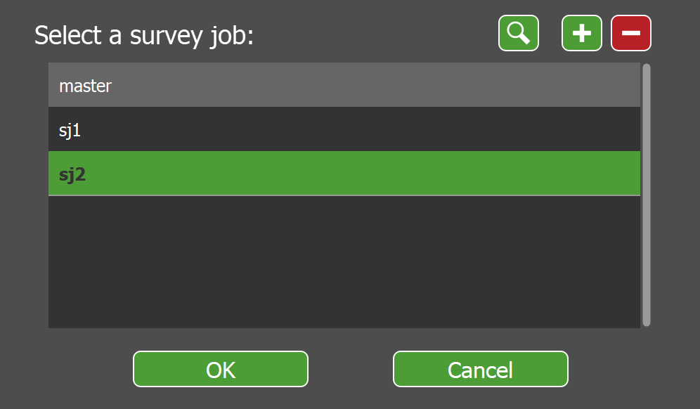
-
Select a database name and tap OK to set it as the survey job.
-
Tap
 to search for survey jobs that match a given text string.
 -
Tap
to create a new survey job. -
Tap
 to delete the selected survey job. This permanently deletes the associated survey job file from the tablet’s internal drive.
-
Survey station locations found in the survey job file are used to populate the Scanner Location field (see Scanner Location).
-
The name of the selected survey job will be incorporated into the scan filename.
See also: Copying files from USB key for how to transfer files including survey station files from a USB key to FieldHHC.
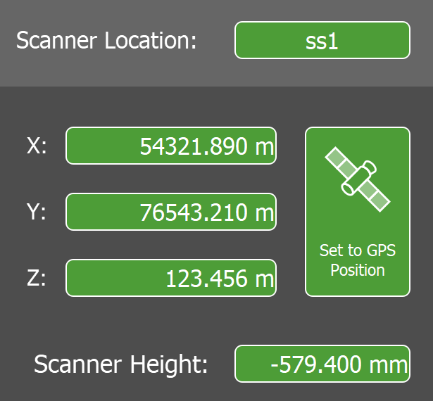
Scanner Location
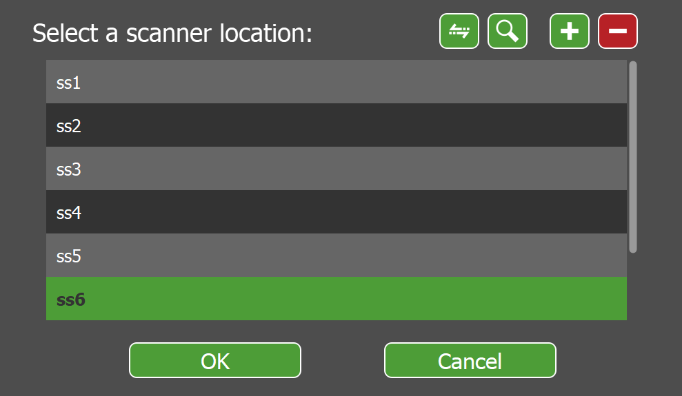
Select the name of the scanner’s setup location and set the location coordinates. Tap the button to display a list of scanner locations in the currently selected survey job.
Note: You do not have to set a scanner location to scan. An alternative workflow is to record the scanner coordinates on the GPS controller. When the job is complete, these locations can be exported to CSV and then imported into PointStudio for use in the Register Scan by Time tool.
|
|
|
Figure 7-19 Scanner location selection panel |
Tip: Survey stations in the master survey job file also appear at the end of the list. To make a scanner location available in other survey jobs, select it and tap ![]() . Copy to master to make the location available to all jobs.
. Copy to master to make the location available to all jobs.
- Select a scanner location and tap OK to set it as the current scanner location.
-
Tap
to search for scanner locations that match a given text string. -
Tap
to create a new scanner location. -
Tap
to delete the selected scanner location from the current survey job.
After selecting the scanner location, you can modify its coordinates as follows:
-
If connected to an external GPS, tap
 Set to GPS Position to set the coordinates to the current GPS position.
 -
Tap any of the X, Y, or Z fields to manually set their values.
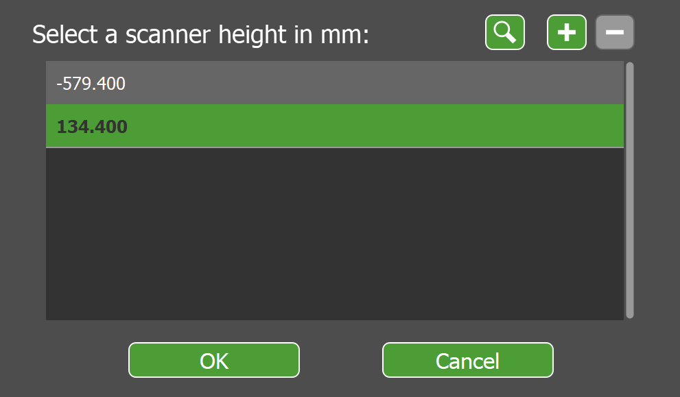
Scanner Height
Set the scanner height. This is the vertical offset of the Scanner Location coordinates relative to the scanner reference level. Tapping the button displays a list of previously saved scanner heights. See Calculating the scanner height for more information on the value to enter here.
|
|
|
Figure 7-20 Scanner height selection panel |
-
Select an existing value and tap OK to set it as the scanner height.
-
Tap
to define a new scanner height. -
Tap
to delete the selected scanner height.
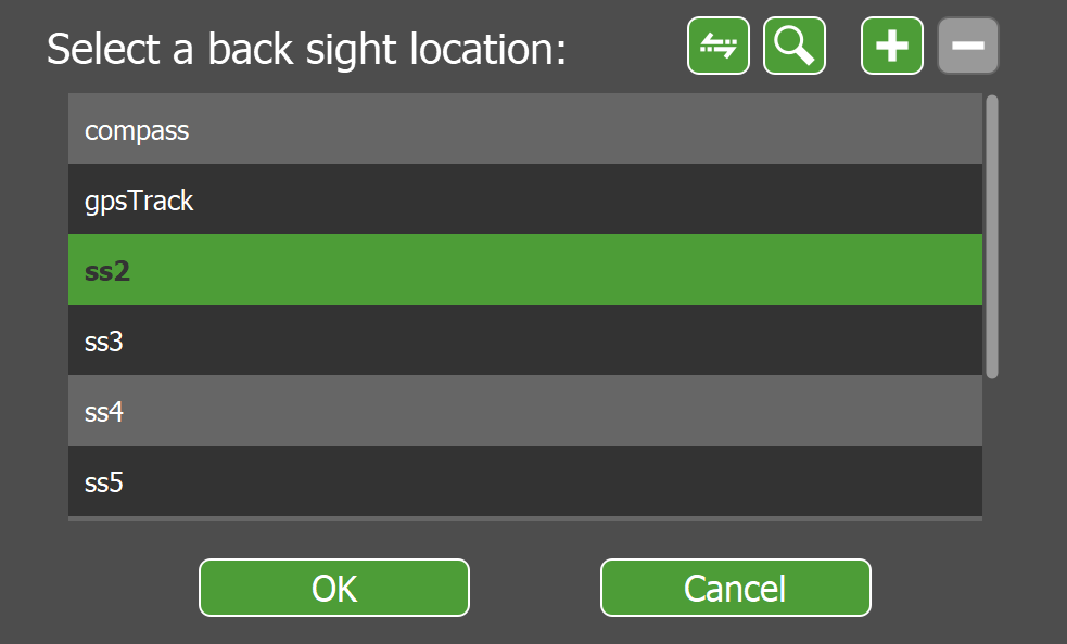
Back Sight
Select the backsight location and set its coordinates. Tap the button to display a list of backsight locations in the currently selected survey job.
|
|
|
Figure 7-21 Back sight selection panel |
-
Select a backsight location and tap OK to set it as the current backsight.
-
Select compass to use the internal compass for the bearing instead of a backsight.
-
Select gpsTrack to use a vehicle’s GPS track to establish the bearing instead of a backsight.
TipTo obtain a heading from the vehicle’s GPS track, drive in a straight line for 5 to 10 metres. The heading is determined by sampling multiple positions as the vehicle moves. For the best results, follow these recommendations:
-
Avoid driving over uneven surfaces.
-
Minimise any variations in the track heading.
-
Avoid letting the vehicle roll back when coming to a stop.
-
-
Tap
 to copy the selected backsight location to another survey job.
 -
Tap
to search for backsight locations that match a given text string. -
Tap
to create a new backsight location. -
Tap
to delete the selected backsight location from the current survey job.
After setting a backsight location, you can backsight the scanner (e.g. using the telescope, if fitted) by orienting the scanner head to point to the backsight location and then tapping Set back sight azimuth. See Backsighting a scanner for detailed instructions.
-
Tap Return to return the scanner head to the previously set backsight azimuth. This can be used to check if the backsight is still valid.
Note: If performing a subsequent scan, tap Return and then check the backsight validity using the scanner’s telescope or aimer. If the backsight is not valid, it suggests the scanner was physically moved between backsighting and the completion of scanning. If this occurs, you will need to establish the backsight again before taking another scan.
Temperature
Set the current temperature. This value is stored with each scan.
Pressure
Set the current pressure. This value is stored with each scan.
Tip: You can enter a pressure directly, or alternatively supply the current altitude and FieldHHC will give the corresponding nominal pressure.
Vehicle compass calibration
Enable this option to apply the compass bearing correction factor if scanning from a vehicle and using the internal compass to provide a bearing.
See also: Calibrating the compass for vehicle use.
Setting up a survey job with multiple backsights
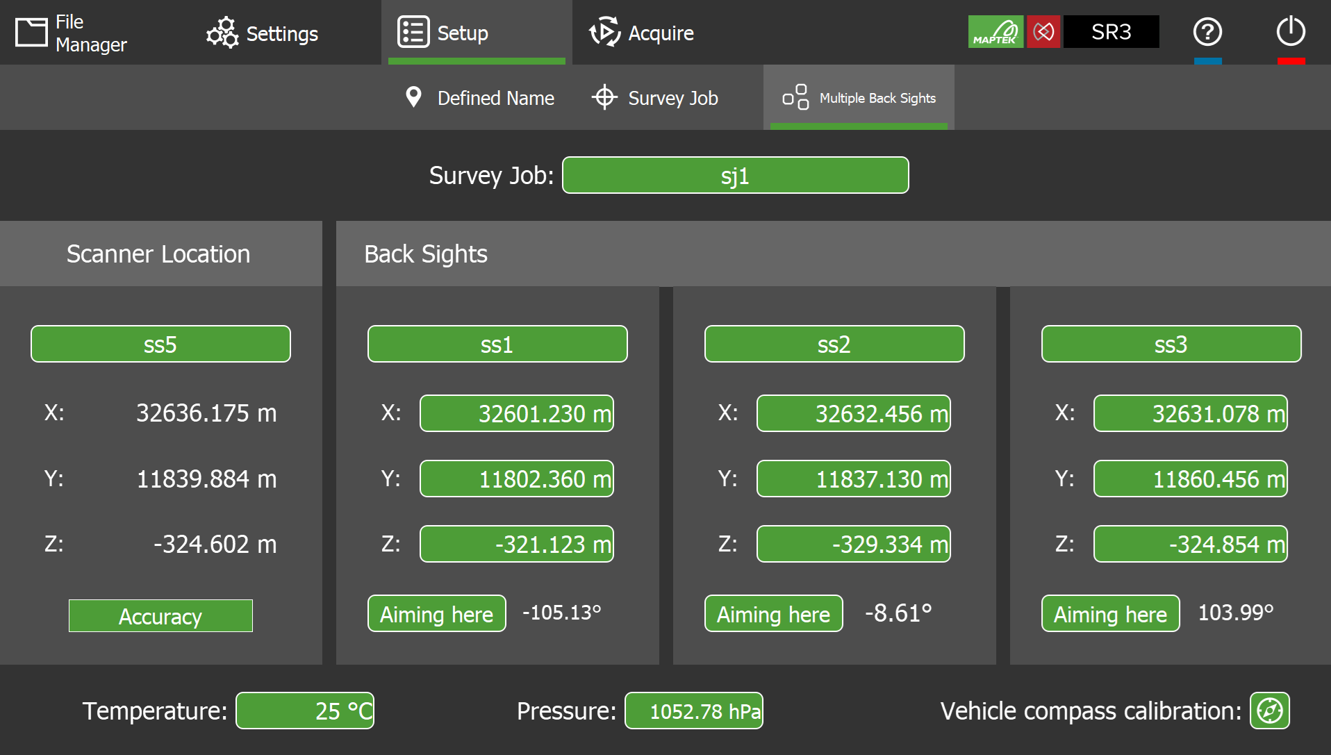
To set up a survey job with multiple backsights, go to Setup >  Multiple Back Sights.
This setup type requires you to backsight the scanner to three known locations (such as survey marks). FieldHHC triangulates the scanner location from the three known locations. This setup type is useful in situation where GPS signals are not available, such as in underground mines.
Note: The multiple backsights setup requires a scanner with a laser aimer or backsighting telescope to accurately backsight the scanner.
|
|
|
Figure 7-22 Multiple Back Sights setup panel |
The recommended workflow for setting up a survey job with multiple backsights is as follows:
-
Before commencing the job, ensure that the surveyed coordinates for the site have been copied to FieldHHC. See Managing non-scan file types for more information.
-
Set up the scanner in a location where three backsights are within line of sight.
Tip: Greater azimuth separation between backsights will yield a more accurate scanner location. Backsights with an azimuth separation of less than 1° will produce an inaccurate scanner location.
-
Connect FieldHHC to the scanner.
-
Go to
Setup > Multiple Back Sights. -
Tap the Survey Job button to select the job containing your backsight locations.
-
Select a database name and tap OK to set it as the survey job.
-
Tap
to search for survey jobs that match a given text string. -
Tap
to create a new survey job. -
Tap
to delete the selected survey job. This permanently deletes the associated survey job file from the tablet’s internal drive.
-
-
Under Scanner Location, tap the <Select location> button to create a new a named scanner location or select an existing one.
Note: If you select an existing location, its coordinates will be overwritten with the new triangulated position after backsighting.
-
For each of the three backsight locations under Back Sights, select a backsight location.
-
Backsight the scanner to each selected location by aiming the laser aimer or telescope to the survey mark, then tapping Aiming Here. See Backsighting a scanner for detailed instructions. The scanner bearing to the given backsight location will display.
When you have completed backsighting the three locations, FieldHHC will record the calculated scanner location with an accuracy indication.
TipThe Accuracy indicator should be green. This confirms good azimuth separation for accurate triangulation of the scanner location. An amber or red indicator indicates low accuracy. In these cases, consider using alternate backsight targets or repositioning the scanner.

Good backsight separation / high accuracy 
Marginal backsight separation / low accuracy 
Poor backsight separation / low accuracy -
Optionally set the Temperature and Pressure fields.
-
Switch to the
 Acquire tab and set your desired Photo Capture, Points, Scan Mode and Point Density settings.
 -
In the viewer, tap
 (Scan multiple backsights) to initiate scanning. FieldHHC will take a small window scan of each backsight target in sequence. You can then configure your scan settings and acquire more scans as required.
Calculating the scanner height
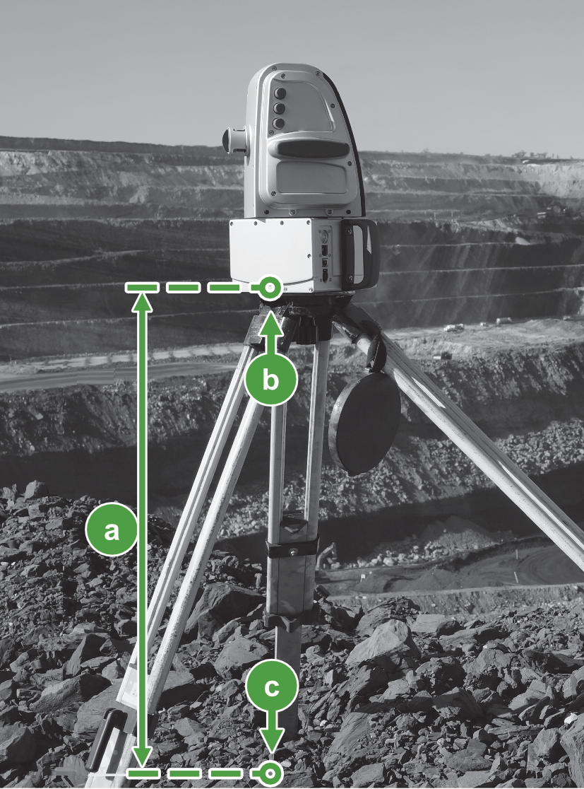
The Scanner Height parameter in survey jobs defines the vertical offset of the scanner reference level relative to the specified Scanner Location. This value is required to locate the origin of scans correctly with respect to the given scanner location.
|
|
|
Figure 7-23 Example scanner height based on GPS position. |
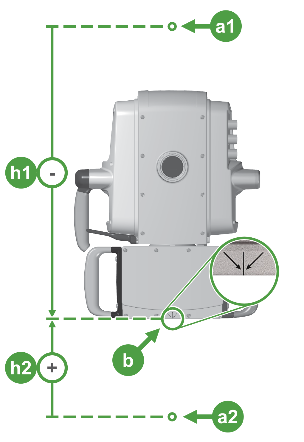
The scanner reference level corresponds to the base of the scanner and is indicated by a marker on the back of the scanner base (see detail  in Figure 7-24). The scanner location is a reference coordinate supplied from one of the following:
-
The GPS position (e.g. when you tap
Set to GPS Position) -
A survey station location (e.g. corresponding to a survey mark)
-
Manually entered location coordinates
The value entered for Scanner Height in Survey Job setups will be positive if the scanner reference level is above the scanner location, or a negative value if it is below the scanner location (see Figure 7-24).
|


By way of example, consider the two following common cases:
-
The scanner location is supplied from a GPS device mounted on top of the scanner.
In this case, the scanner height is equivalent to the GPS offset that defines the vertical offset of the scanner reference level relative to the GPS position. See Calculating the GPS offset for details. You can tap Set to GPS Position in the Survey Job panel and then enter a negative value for Scanner Height. -
The scanner location is supplied from a survey mark located below a tripod-mounted scanner.
In this case, you specify the scanner location corresponding to the survey mark, either by selecting it from a survey job file, or by manually entering the coordinates. Then, measure the vertical distance from the survey mark to the scanner’s reference marker and enter this as a positive value for Scanner Height (see Figure 7-24).
Scanner height
Scanner reference marker 
Survey mark location
Backsighting a scanner
Backsighting a scanner means orienting the scanner head to point in the direction of a known location or backsight for the purpose of establishing the correct orientation of scans in the XY plane.
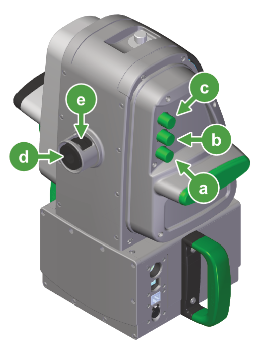
Note: All R3 MkII scanners have an azimuth knob located on the scanner head, which can be used to rotate the head to a desired azimuth position. For precise backsighting, a scanner with either a backsighting telescope (XR3-CT) or a laser aimer (SR3) is required.
To backsight a scanner equipped with either a telescope or laser aimer, follow these steps:
-
Flick the azimuth knob with a quick motion to traverse the scanner head until its window is pointing in the approximate direction of the backsight location. To stop the scanner head, turn the azimuth knob in the opposite direction.
-
Establish the backsight.
If using a telescope:
Refer to Figure 7-26 to locate the relevant backsighting controls.
Telescope elevation control knob
Telescope focus knob 
Telescope eyepiece 
-
Look through the telescope eyepiece (
) and use the focus bezel () to bring the crosshairs into sharp focus. -
Use the scanner’s azimuth (
) and elevation () control knobs and to locate the backsight target within the crosshairs.-
Use the telescope focus knob (
) on the scanner head to focus the backsight target as required. -
Use the eyepiece focus bezel (
) to focus the crosshairs.
Tip: By moving your eye across the eyepiece, you can determine if your eyepiece and objective focus have converged. If your focus is correct, the vertical crosshairs should be stationary. If the reticule moves left and right against the view, continue to adjust your focus.
-
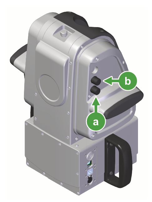
Refer to Figure 7-27 to locate the relevant controls on an SR3 scanner.
Aimer elevation control knob -
Rotate the elevation control knob (
) or tap  in the Setup tab to turn on the aimer.
 -
Use the scanner’s azimuth (
) and elevation () controls to align the aimer’s red laser beam to the backsight target.
-
-
Set the backsight in FieldHHC.
This will be in the
Setup tab, in one of the following setup types:-
Survey Job: In the Back Sight section, tap Set back sight azimuth. See Setting up a survey job for the full procedure.
-
Multiple Back Sights: Tap Aiming here under the appropriate backsight location field. See Setting up a survey job with multiple backsights for the full procedure.
-