Configuring FieldHHC
Settings tab
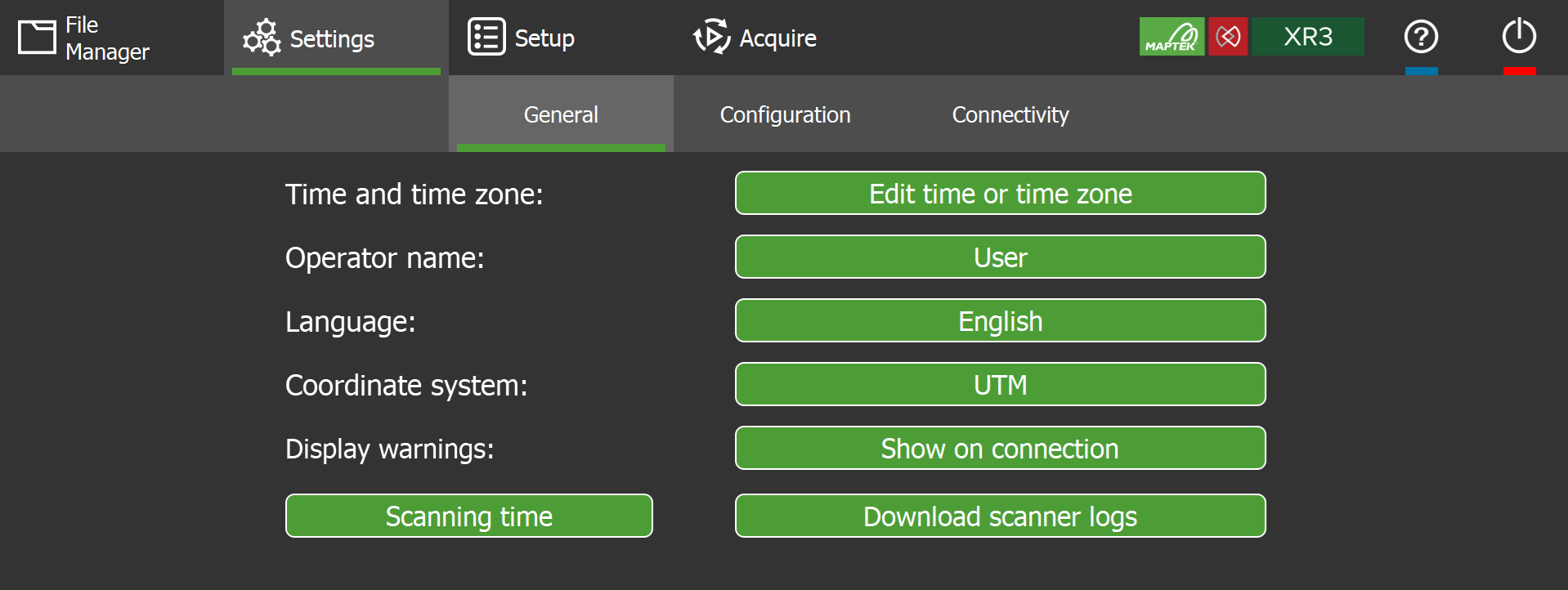
The  Settings tab allows you to configure global FieldHHC settings. The tab is further split into the General, Configuration, and Connectivity subtabs.
|
|
|
Figure 7-7 FieldHHC Settings tab |
General settings
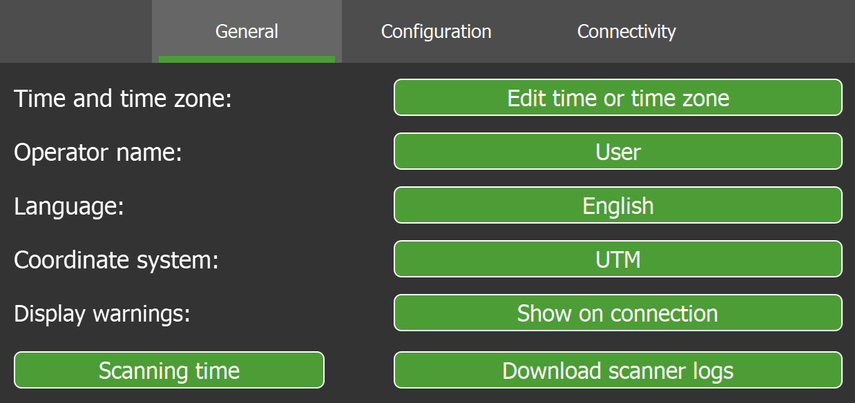
The Settings > General subtab allows you to configure general system settings such as time, language, and coordinate system.
|
|
|
Figure 7-8 General settings subtab |
| Set the system date and time. | |
|
Select or manage operators. The selected operator name is recorded with new scans.
|
|
|
Select the display language. FieldHHC supports the following languages:
|
|
| Select the coordinate system to apply to new scans. The default and only initial coordinate system is UTM. Additional coordinate systems can be exported from PointStudio and added to FieldHHC. See Managing non-scan file types for more information. | |
|
If the Show on connection button is active, it means one or more warning messages that usually appear on startup were disabled by choosing Do not show this warning.
If the button is not active, it means the warning messages are enabled and will be displayed periodically. |
|
|
Display the following details of a connected scanner:
|
|
|
Download logs from a connected scanner to USB.
|
|
| Disconnect | Force a disconnection from a connected scanner without closing FieldHHC. The previously connected scanner serial number is displayed next to the button. |
 to search for operators that match given text.
 to create a new operator name.
 to remove the selected operator. Note: The currently selected operator cannot be removed.
Configuration settings
The Settings > Configuration subtab allows you to perform configuration related to units, licences, feature codes, and scanner setup (including Maptek Drive mount offsets).
|
|
|
Figure 7-9 Configuration settings subtab |
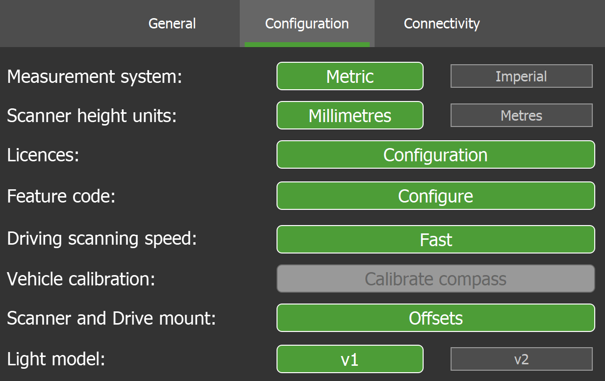
| Select the preferred system of measurement. | |
| Select the unit of measurement to use when defining the scanner height. | |
|
Apply licences for advanced tools and configure settings for design conformance.
See Licensing advanced tools and Configuring design conformance settings for more information. |
|
| Select the active feature code set to use when making annotations. See Feature codes for more information. | |
|
Set the scanning speed (scan mode) to use when acquiring driving scans. The options are as follows:
Note: Increasing the scanning speed while driving on rough terrain or operating in a cold climate (see Scanning in cold conditions) may reduce the ability of the scanning mirror to maintain a constant rotation rate. Cold climate and sufficiently strong induced vehicle rolling and pitching motion may cause the error message “Elevation Error: Requested speed not reached” to be logged. If these errors are being frequently reported, reduce the scanning driving speed to a slower setting and decrease the vehicle’s speed accordingly. |
|
| Perform compass vehicle calibration. See Calibrating the compass for vehicle use for details. | |
|
Scanner and Drive mount |
Configure scanner and Drive vehicle mount offsets. See Configuring scanner and Drive vehicle mount offsets for details. |
| Select the lighting model to use with a Maptek underground lighting system. The light model setting optimises the camera to the type of underground lighting system used. |
Connectivity settings
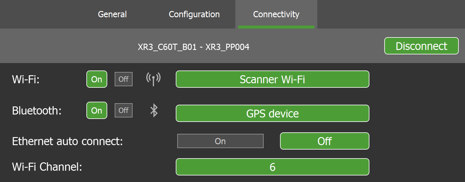
The Settings > Connectivity subtab allows you to configure connectivity settings including wireless scanner selection and Bluetooth GPS connection.
|
|
|
Figure 7-10 Connectivity settings subtab |
| Wi-Fi |
Configure the FieldHHC tablet’s Wi-Fi connectivity and select a wireless scanner.
See Connecting to a scanner wirelessly for more details. |
| Bluetooth |
Configure the FieldHHC’s Bluetooth connection to an external GPS.
See Connecting to a Bluetooth GPS device for more details. |
| Ethernet auto connect |
When enabled, this will automatically connect FieldHHC to a scanner plugged in with an Ethernet cable.
|
| Wi-Fi Channel | Select the Wi-Fi channel to use when connecting to a scanner with a wireless connection. This may improve signal quality when significant Wi-Fi traffic or radio interference is present. |
| Disconnect | Force a disconnection from a connected scanner without closing FieldHHC. The previously connected scanner serial number is displayed next to the button. |
Calibrating the compass for vehicle use
R3 MkII scanners have a built-in magnetic compass for use in determining the scanner’s bearing. Vehicle compass calibration is necessary for eliminating the vehicle’s interference with the compass. Calibration is required prior to first use, with recalibration required at approximately six-monthly intervals.
To calibrate the compass for vehicle use, follow these steps:
-
Mount the scanner on the vehicle and connect to it with FieldHHC.
-
Ensure the vehicle is in a wide, flat area where the scanner can receive GPS signals.
-
In
Settings > Configuration, tap Calibrate compass.The Vehicle Compass Calibration dialog opens.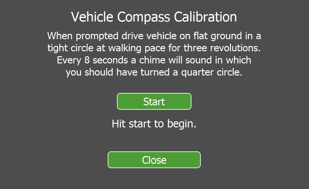
Figure 7-11 Vehicle compass calibration panel
-
When prompted, begin driving in a tight circle. Maintain a constant speed of about 8 seconds per quarter circle until three full turns have been completed.
Tip: During this process, listen for the chimes to aid in maintaining the correct turning rate as you drive. When calibration completes, the magnetic calibration profile is saved.
Note: If the rate of rotation is not correctly maintained, magnetic interference sources are present, or the GPS signal is lost, the calibration will fail and an error notification is displayed. If so, remedy the cause and try again.
Important: You will need to apply the compass calibration factor when acquiring vehicle mount scans that require the built-in compass. To enable the calibration factor, make sure the Vehicle compass calibration toggle on the  Setup tab is enabled (
 ).
).
Configuring scanner and Drive vehicle mount offsets
To configure scanner and Drive vehicle mount offsets, go to Settings > Configuration > Scanner and Drive mount and tap Offsets.
|
|
|
Figure 7-12 Scanner and Drive vehicle mount offsets panel |

The settings are explained as follows:
-
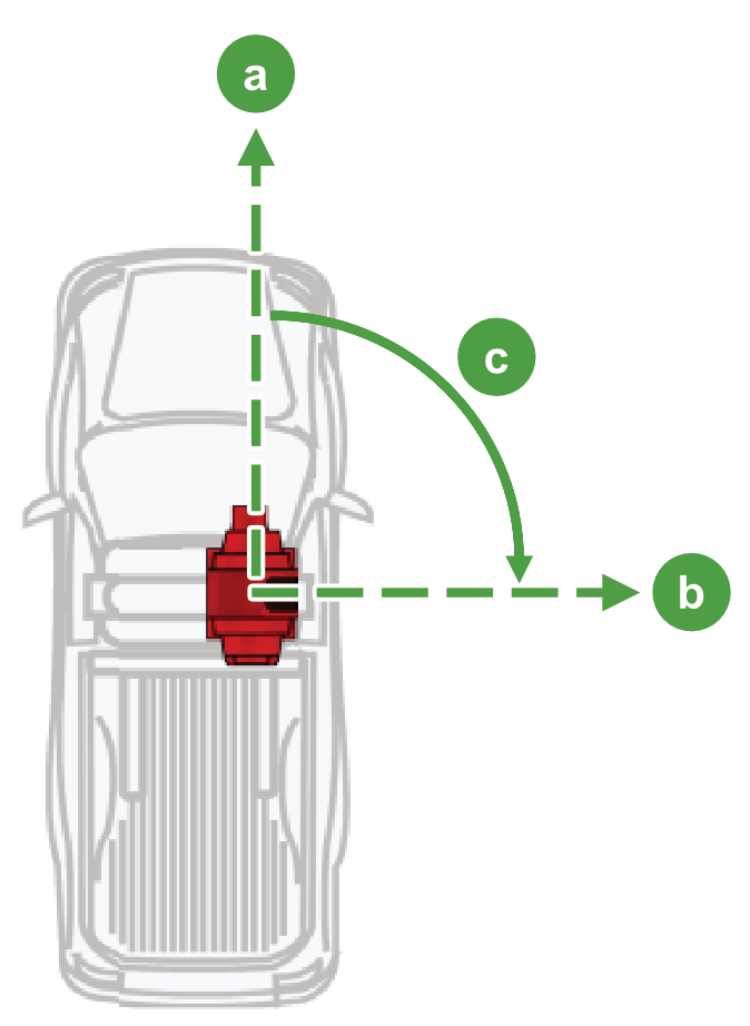
Scanner to forward offset. This informs both gpsTrack and the Drive system of the orientation of the scanner with respect to the forward direction of the vehicle. The scanner to forward offset is measured as the clockwise angle from the vehicle’s forward direction to the scanner’s zero azimuth position (see Figure 7-13). A negative value indicates a counterclockwise angle. If the scanner is mounted on the vehicle facing backwards, this value should be 180°.

Vehicle forward direction

Scanner zero azimuth position 
Scanner to forward offset -
Defined name GPS offset. This defines the vertical offset of the scanner reference level relative to the GPS position. See Calculating the GPS offset for more information.
-
Scanner orientation at rest. This sets the direction the scanner head should face when powered on but not scanning. The value is relative to the scanner’s zero azimuth position.
Important: To protect the scanning window from stone chips while driving at speed, it is recommend that single-window scanners face backwards, and dual-window scanners face out perpendicular to the vehicle’s direction when not scanning. Assuming the scanner is mounted facing backwards, this means setting the Scanner orientation at rest value to 0° for single-window scanners and 90° for dual-window scanners.
-
Drive offsets. These are needed by the Drive system to calibrate the scanner to the vehicle mount system. This is initially set up at the factory. Recalibration by the user is required if the mount plate is removed from the scanner or if a different scanner is to be used with the drive system.
-
Heading, Pitch, and Roll offsets. These are calibration factors generated with scans using the Calibrate INS to scanner orientation tool in PointStudio.
-
RTCM height offset. This compensates for some GPS base stations not sending the antenna reference point to phase centre correctly in the RTCM message.
-
Calculating the GPS offset
The GPS offset is the vertical distance offset of the scanner reference level relative to the GPS position output by an external GPS device. This offset is necessary to correctly position scans in defined name and survey job scan setups that use an external GPS. Since the GPS receiver is usually mounted on top of the scanner, the offset is typically supplied as a negative value to indicate that the scanner reference level is below the GPS position. The scanner reference level corresponds to the base of the scanner.
Note: The GPS position depends on how the GPS device has been configured. In the examples below, the GPS position is assumed to coincide with the GPS antenna phase centre. If the GPS device is configured to output the GPS position corresponding to a different point, the GPS offset needs to be calculated accordingly.
|
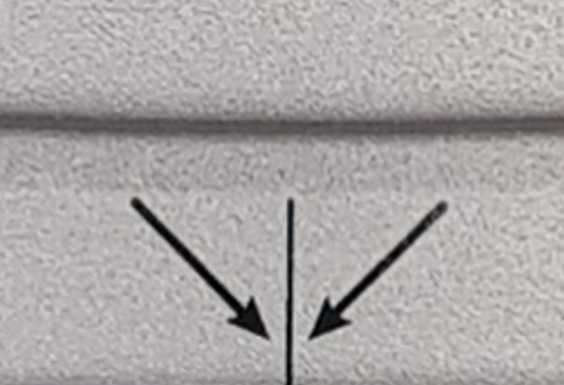
The scanner reference level (corresponding to detail ) is marked on the back side of the scanner base.
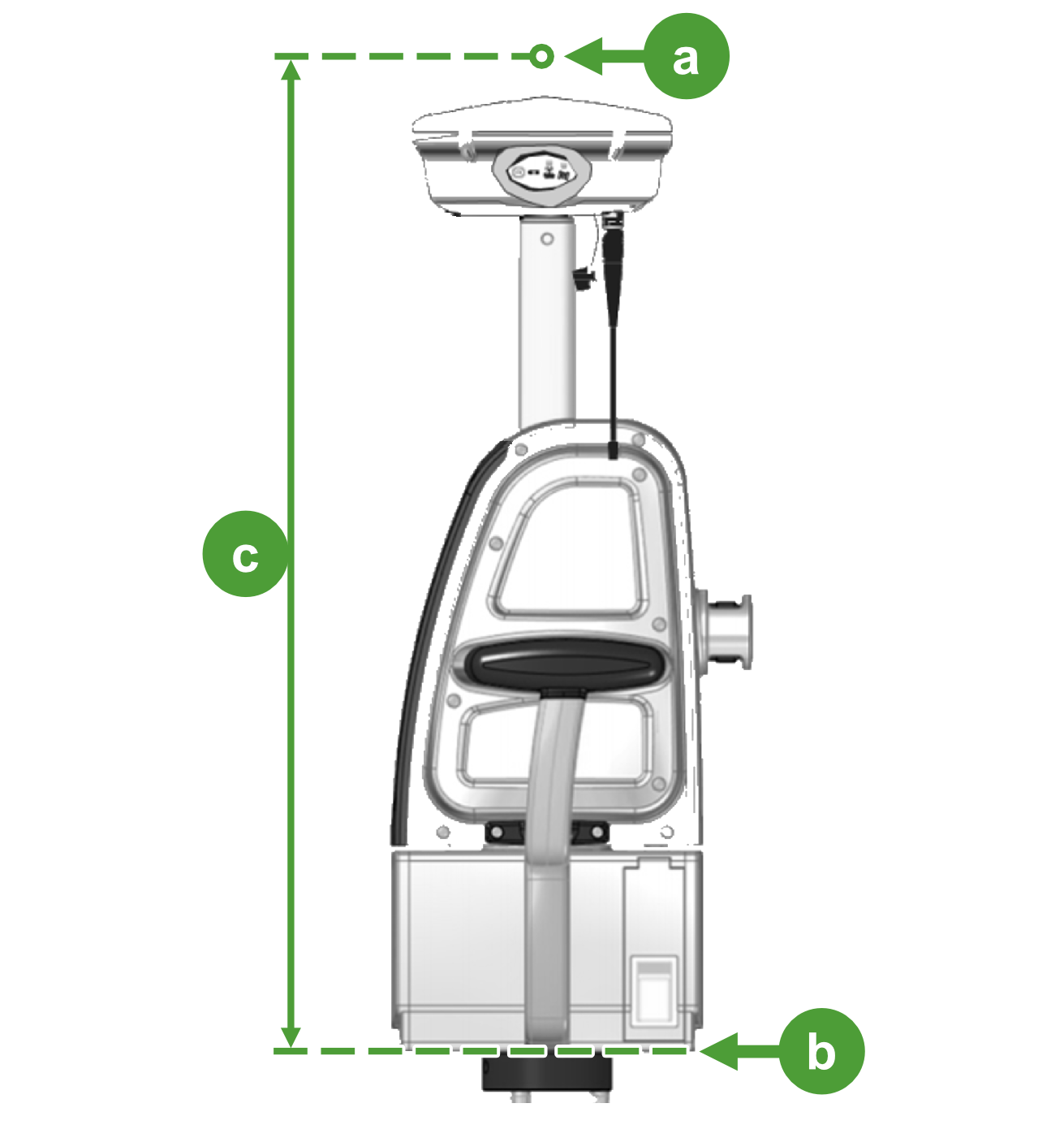
In this example, we calculate the GPS offset for a typical configuration where the GPS unit is mounted on top of the scanner using a spacer (see Figure 7-15). The GPS position is assumed to correspond to the GPS antenna phase centre.
|
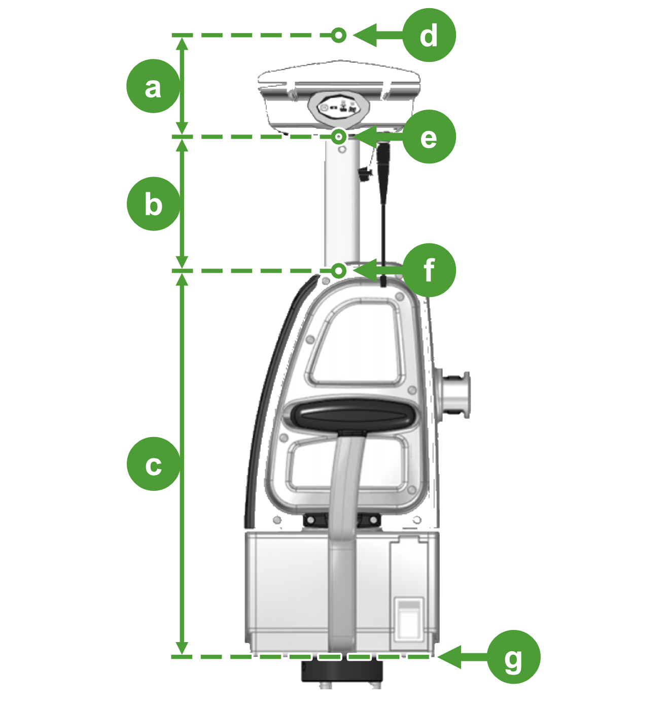


The GPS offset is the sum of the GPS antenna phase centre offset (a), the spacer height (b), and the scanner height to UNC thread (c), expressed as a negative value:
GPS offset = -(a + b + c)
- From the GPS unit documentation, we find that the GPS antenna phase centre offset (a) measured from the bottom of the GPS unit (e) is 64.9 mm.
- The spacer height (b) is 139 mm.
- The scanner height to UNC thread (c) for this scanner is 375.5 mm (see Table B-1).
So in this example, the GPS offset is given by:
GPS offset = -(64.9 + 139 + 375.5) = -579.4 mm.
In this example, we would enter the value -579.4 mm in one of the following fields as required:
 Survey Job
Licensing advanced tools
Some tools, including advanced registration and design conformance, require a licence before they can be used.
Note: Licences are bound to a scanner’s serial number and will not work with data acquired from other scanners.
Tip: To check whether you have a licence, go to Settings > Configuration > Licences and tap Configuration. Tap Licensed scanners to inspect the details of the licence.
To licence advanced tools:
-
If you do not have a licence, request one from your Maptek representative. Please quote the scanner’s serial number and request a “conformance licence”. The licence will usually be delivered to you via email.
-
Save the licence file license.mlf to the root folder of a USB key.
-
Insert the USB key into the FieldHHC tablet. Installation occurs automatically and confirmation appears in the status bar.
-
To confirm licence installation, go to
Settings > Configuration > Licences and tap Configuration. Tap Licensed scanners to inspect the details of the licence.
Connecting to a Bluetooth GPS device
To connect to a Bluetooth GPS device:
-
Turn on the Bluetooth GPS device.
-
In FieldHHC, go to
Settings > Connectivity and do the following:-
Make sure Bluetooth is enabled by tapping On.
-
Tap the button labelled GPS device.
-
Select the GPS device from the list of available devices.
-
Tap Save.
FieldHHC will connect to the GPS device.
-
