Viewing scans
Once scans have been acquired, you can view them on the  File Manager tab. This section discusses the viewing tools. For information on file management operations such as transferring and archiving, see File management.
Viewing scans in panoramic mode
Figure 7-37 shows the panoramic scan viewer. It displays a panoramic image of the current highlighted scan from the perspective of the scanner.
-
Tap a scan’s row in the Scans list to highlight it and display it in the panoramic viewer.
-
Drag anywhere on the image to pan.
-
Tap the
 (Zoom in) button to zoom in on the scan. This hides the scans list and enables the annotation tools. Tap
  (Exit) to exit zoomed in mode.
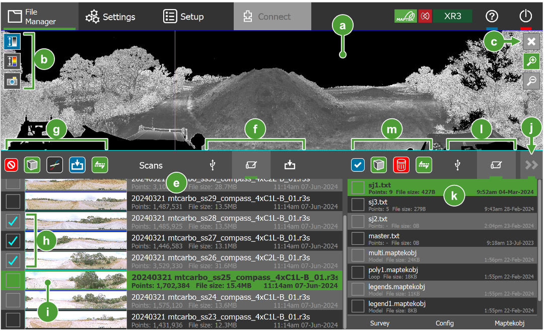

|
Panoramic scan viewer |
|
||||||||||||

|
|
|||||||||||||

|
Exit current view |
The |
||||||||||||

|
|
|||||||||||||

|
This lists the scan files in the selected scan repository ( |
|||||||||||||

|
See Transferring, archiving, and deleting scan files for more information. |
|||||||||||||

|
Scan selection tools |
These tools operate on scans selected in the Scans list ( See Transferring, archiving, and deleting scan files for more information on transferring and archiving. |
||||||||||||

|
Selected scans |
|
||||||||||||

|
Highlighted scan |
The highlighted scan appears in the panoramic viewer. |
||||||||||||

|
Files drawer toggle button |
Tap to hide or show the files drawer. |
||||||||||||

|
Non-scan files appear here. See Managing non-scan file types for details on managing non-scan files. |
|||||||||||||

|
|
|||||||||||||

|
File selection tools |
|


Scan colour schemes
Scans can be coloured in three ways, as follows:

Annotating scans
The annotation tool allows you to draw freehand lines to identify features of interest on a scan. Annotations are stored with the scan, and can be viewed in FieldHHC’s panoramic or 3D viewers, or in PointStudio.
|
|
|
Figure 7-38 Annotations drawn on a scan in the panoramic viewer. |
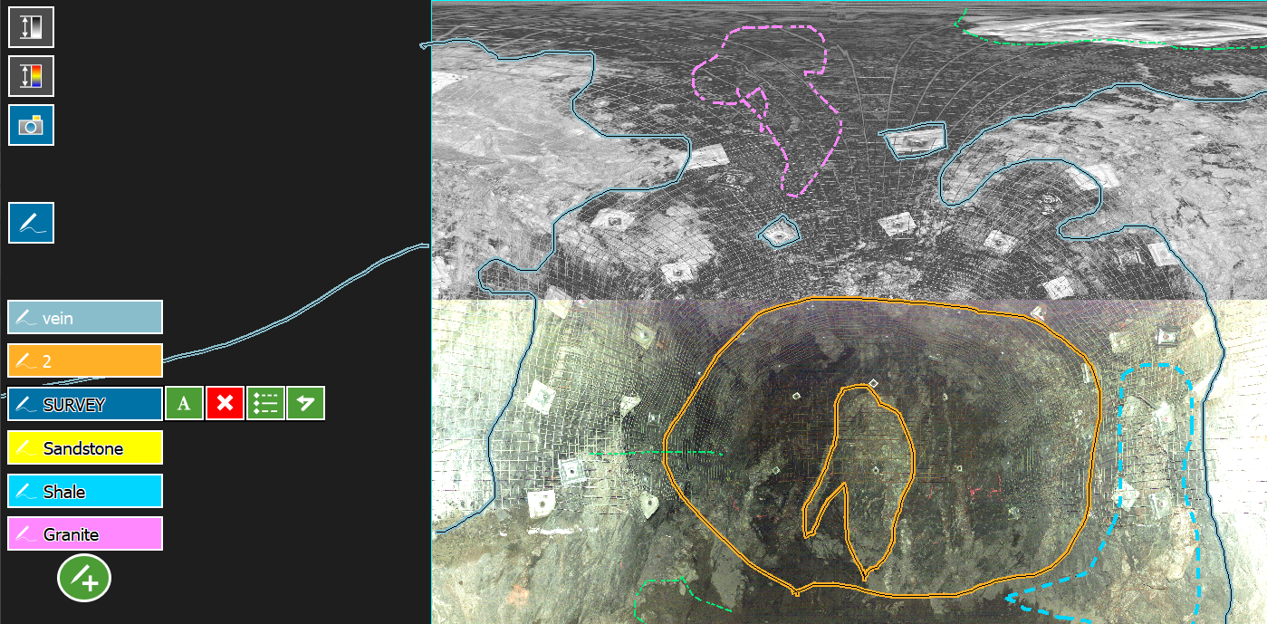
Tip: Annotations are drawn in the ‘zoomed in’ mode of the panoramic viewer. Tap the (Zoom in) button to view annotations and use the annotation tools. The  (Add annotation) button should appear when you zoom in. If not, annotations may be hidden. Tap the
  (Show/hide annotations) toggle to show annotations and reveal the button.
Creating annotations
To create an annotation:
-
Make sure you are on the
File Manager tab and the scan you wish to annotate is highlighted in the Scans list. -
Tap the
(Zoom in) button to show the annotation tools. If annotations are hidden, tap the (Show/hide annotations) toggle. -
Tap the
(Add annotation) button. A new annotation label appears on the screen. -
If you have selected an active feature code set in
 Settings, a dialog will appear that allows you choose a style for your annotations. Select the desired feature code and tap Apply. If there is no active feature code set, the default feature code style will be used for annotations.
 -
Use the stylus to draw an annotation on the scan. You can create more than one annotation line for a single label.
Note: Annotations are initially given a label based on the feature code name. If the default feature code is used, the label will be based on an increasing number starting at 1.
-
Tap the annotation’s label field to stop annotating and return the view to pan mode.
Editing annotations
After creating an annotation, you can edit it as follows:
-
Tap an annotation’s label field to select it for editing and show its controls, explained below.


Edit the annotation label.

Delete the annotation.

Set the annotation’s feature code (change its style).

Undo the previously drawn line. 
Redo a line that was undone. -
Continue drawing on the scan image to add new lines to the selected annotation.
-
Tap the annotation’s label field to stop annotating and return the view to pan mode.
Showing and hiding annotations
You can show or hide annotations in both the panoramic viewer and the 3D viewer.
-
Tap the
 (Show/hide annotations) toggle to show or hide all annotations.
 -
In the 3D viewer, while annotations are showing, tap the
 (Show/hide labels) toggle to show or hide annotation labels only.
Feature codes
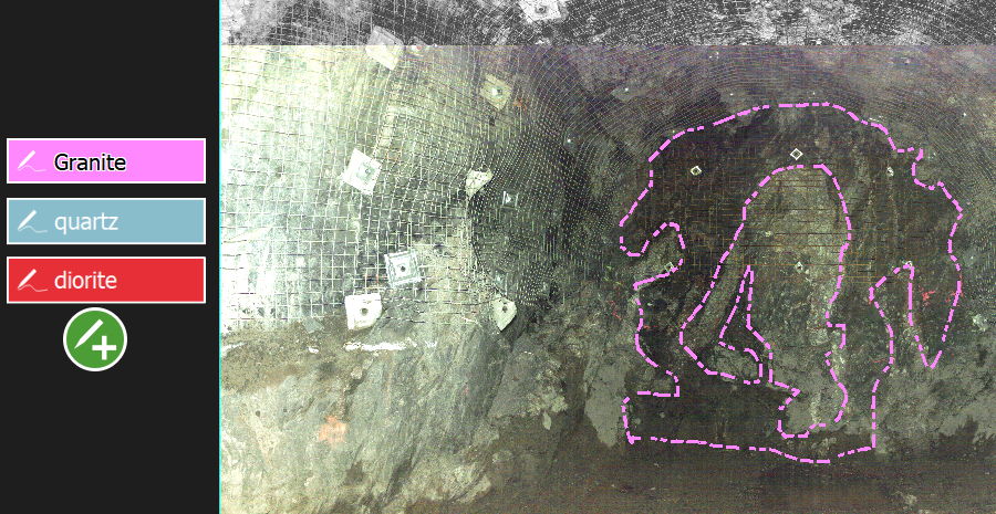
Feature codes are named line styles that you can apply to annotations. By default, FieldHHC will create annotations as solid lines using a unique colour for each new annotation. By creating your own feature codes, you can use a consistent custom annotation style for a given feature type, such as a resource type or geological feature. You can have multiple sets of feature codes available in FieldHHC and set a single one as the active set to use for new annotations.
|
|
|
Figure 7-39 A example custom feature code set. |
Creating feature codes
Features codes need to be created in PointStudio and then copied into FieldHHC.
To create feature codes in PointStudio:
-
Go to the Features tab in the PointStudio preferences.
-
Select New... from the Profile drop-down to create a new feature set.
-
Click Add... to create a new feature. Configure the following fields for the feature as desired:
-
Name
-
Colour
-
Thickness
-
Style
Note: The other feature fields are not used in FieldHHC.
-
-
Continue adding new features for every named style you want.
-
Click Export... to export the feature code set to a JSON file (.json).
Consult the PointStudio help for more information on feature codes.
Setting and using the active feature code set
After creating feature codes and exporting them from PointStudio, you can use them in FieldHHC as follows:
-
Copy the JSON file defining a feature code set into FieldHHC. See Copying files from USB key for detailed instructions.
-
Set the active feature code set. The active feature code set affects which feature codes or styles are available for selection when creating new annotations.
To set the active feature code set:
-
Go to
Settings > Configuration. -
Tap the button next to Feature code.
-
Select the filename containing the desired feature code set from the list and tap Apply.
-
-
Create annotations as normal. When you create a new annotation, you will be prompted to select a feature code. The new annotation’s initial label will be taken from the feature code name, and the feature code’s style will be applied to the annotation lines.

Viewing scans in 3D
You can view scans and other data in 3D. The FieldHHC 3D viewer allows you to access other tools including design conformance, in-field registration and advanced registration.
-
To view scans in 3D, select one or more scans in the Scans list, and then tap the
 (View in 3D) button.
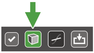
-
To view other object types in 3D, select them in the Files drawer, and then tap the
(View in 3D) button. -
To exit the 3D viewer and return to the panoramic viewer, tap the
button (see in Figure 7-40).
3D viewer and controls

|
|
Scan colour schemes |
See Scan colour schemes for more information. |
||||||||||
|
|
View modes |
|
||||||||||
|
|
Measure tool |
Tap
|
||||||||||
|
|
Manual positioning tools |
See Manually positioning scans for details. |
||||||||||
|
|
Annotation toggles |
|
||||||||||
|
|
Exit 3D view |
Tap |
||||||||||
|
|
Zoom controls |
|
||||||||||
|
|
Back face points toggle |
See Hiding back face points for details. |
||||||||||
|
|
Registration tools |
See Registering scans for details. |
||||||||||
|
|
Undo and redo |
|
||||||||||
|
|
Scale bar | Gives an indication of the scale of distances at the current zoom level. | ||||||||||
|
|
Compass and scan origin |
|
 to turn on the measure tool. Drag a line between two points to measure the distance between them.
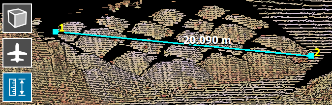


Panning, zooming, and rotating the view
Use the following methods to pan, zoom, and rotate the view, depending on the current view mode.
 Z-Up view
 |
 Aerial view
 |
|
|---|---|---|
| Pan |
|
|
| Zoom |
|
|
| Rotate |
|
(Rotation is disabled in aerial view mode.) |
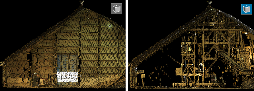
Hiding back face points
When scanning inside an enclosed space such as indoors or underground, the resulting scan contains points representing walls, roofs, and other surfaces that can obscure your view of the inside of the scanned space. These points are called back face points because they represent the back side of the surface when viewed from a given camera angle. You can hide these points to obtain a better view of the interior surface.
-
Tap the
 (Show/hide back face points) button to toggle between showing or hiding back face points (see in Figure 7-40). When enabled, back face points are hidden. Because back face points are defined by the current camera angle, the points hidden or shown will change dynamically as you rotate the view.
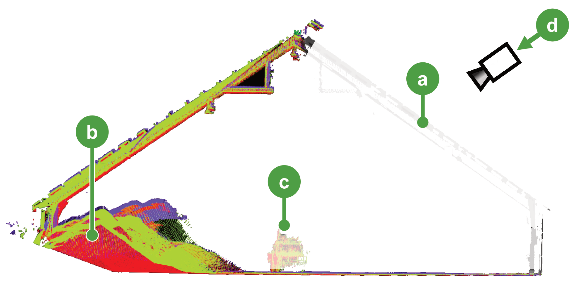
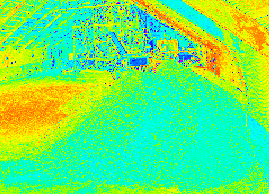
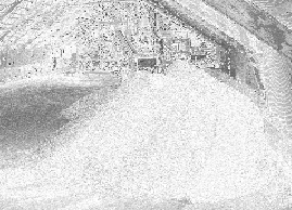
|
|
|
Figure 7-41 Comparison of a scan viewed with back face hiding disabled (left) and enabled (right). |
|
|
|
Figure 7-42 Hiding back face points (a) allows the interior parts of a scan (b) to be visible. The scanner origin (c) is used to determine which points are back-facing for the current camera angle (d). |