Setting preferences
Source file: preferences.htm
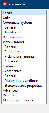
The Preferences panel is used to change language, date, units, registration tolerance, view window, toolbar and advanced system options.
-
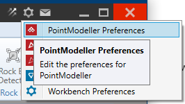
Go to the
 preferences cog.
 -
Select PointModeller Preferences.
To set up the primary language go to Workbench help for more information.
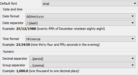
Locale
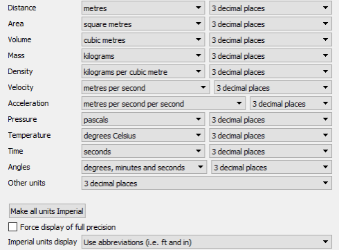
Units
If no unit preferences have been set (for example, on first startup of the application), the software will use the computer location (Metric or Imperial unit systems) and the appropriate base unit to three decimal places. For example, if the language is set to English with a distance of 0.06m, it will display it as 0.060m. However, if the language is set to English (United States), then the same distance would display as 0.196ft.
Setting the
Distance unit field to metres
will display the distance as 0.060m regardless of the location.
Setting the Other units field will set the precision for all values that don't use one of the specified unit dimensions. For example, if the field is set to two decimal places, and a standard error value of 0.061234 is to be displayed, then the value will display as 0.06.
The Imperial units display drop-down is used to specify how feet and inches should be displayed, for example, 6ft 2in or 6' 2".
A value displayed at full precision is displayed using scientific notation at its full precision (64 bit floating point value precision is roughly 16 decimal places).
The Force display of full precision option will display all values (regardless of their unit or lack of one) at full precision.
Coordinate systems - General
The coordinate system manager can be set up in these preferences. The manager can be populated with a list of coordinate systems for selection later using Define coordinate system and Convert coordinate system. A default coordinate system can be assigned for imported scans. Further buttons allow you to add entries to the list, edit, delete, import and export coordinate systems.
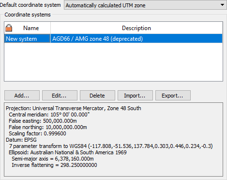
Coordinate systems - Transform
![]()
Registration
Default registration tolerances can be set with this option. The values required are for Horizontal and Vertical bounds.
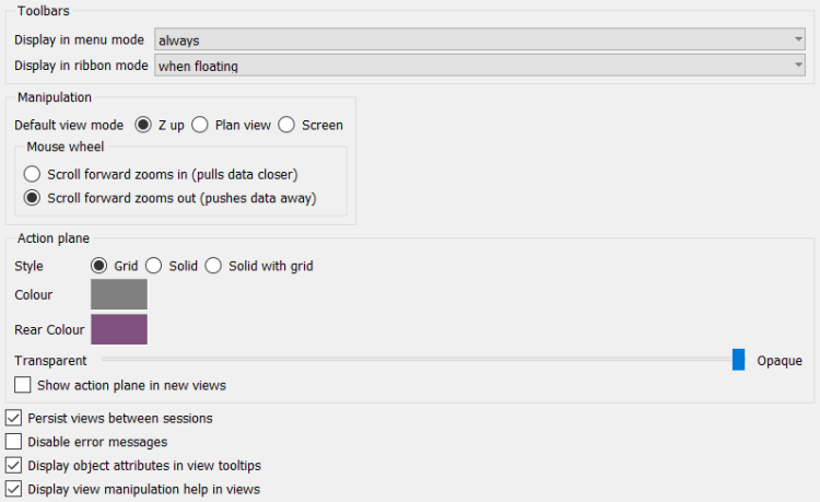
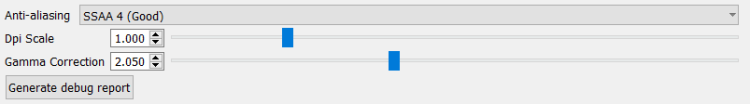
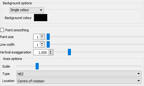
View windows
This option
sets the default window view and the behaviour of the mouse when zooming.
Zooms data has the effect of zooming
in with the mouse wheel rotating forwards. Zooms
camera sets the opposite behaviour, zooming out with the
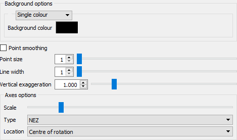
mouse wheel rotating forwards. Other attributes can be set such as default
background colour, point size, line width and axes options, LOD and associated
frame rate.
View windows - General
View windows - Properties
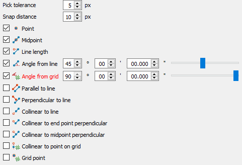
View windows - Picking and snapping
View windows - Advanced
Features
This option allows for creating custom attributes that can be applied to either point, lines or polygons.
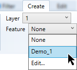
To create Features to add to objects do the following: first The features and attribute created will appear in the Feature drop down list of options found in the Create ribbon tab in the Draw group.
-
Click the Profile for the following options:
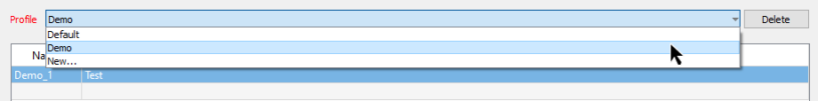
- By selecting Default, you can create features and attributes that will be set as the default features and attributes for your objects.
Note: The Default profile cannot be deleted.
- Selecting a profile name (in the example above Demo) will list the features that are set to the Demo profile, (in this example Demo_1) feature.
- Selecting New..., will prompt you to create a new profile with a new name to add features to.
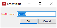
- The selected profile can be removed by clicking the Delete button on the far right.
-
Clicking on the feature name gives you the following options that are accessible from the bottom of the panel:


- Add...: To create a new set of features and attributes.
- Edit...: To edit the selected features and attributes.
- Remove: To remove the selected feature set.
- Import...: To import a feature shared or created on another PC.
- Export...: To export a feature and share or to use on another PC.
To create a set of features to apply to objects follow these steps:
-
Select a Profile to list the features created or create a new profile.
-
Select a feature to edit by clicking the features name.
-
Click Add... or Edit...

Define Feature panel will open to edit the features pertaining to selected feature set.
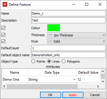
In the Define Feature panel you can:
- Change the name of the feature. Give it a Description.
- Change the colour of the feature. Set the colour by selecting the checkbox and clicking the Colour swatch.
- Change the line thickness. Set the line thickness by selecting the checkbox then clicking the Thickness drop down list.
- Change the line style. Set the line style by selecting the checkbox then clicking the Style drop down list.
- Change the Default layer this feature will be added to.
- Set a Default object name, which will be given to objects created with this feature.
- Define the Object type for these features and attributes. They can be: Points, Lines or Polygons.
- Optionally, set additional Attributes that will also be assigned to the object.
Or
-
Click in the empty row below the features list.
-
Click Add....
-
Use the information in the previous step to set up your new features.
-
Click OK or Apply.
A blank Define Feature panel will open to create your new features.
![]()
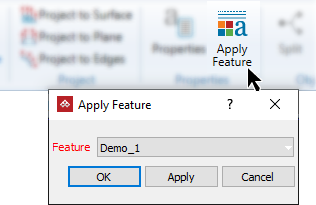
These features can now be accessed easily either from the Draw group in the Create tab, or from the Properties group in the Edit tab to be applied quickly.
Geotechnical - General
Option to display discontinuities by their dip direction and angle or strike direction and angle in 3D view.
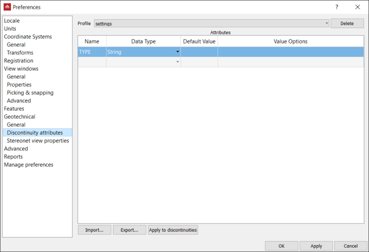
Geotechnical - Discontinuity Attributes
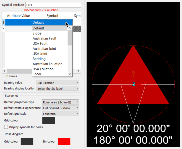
Geotechnical - Stereonet View properties
Characteristics of window displaying Stereonets
Advanced
-
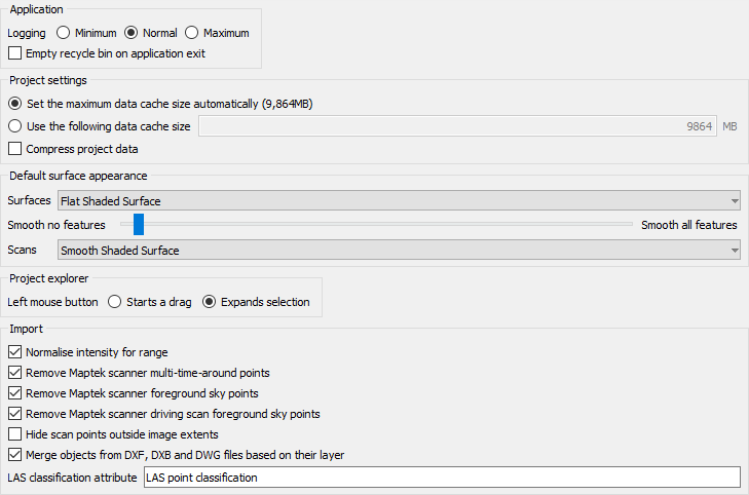
The Application logging options on the Advanced tab displays the logging setting. The logged data is used to assist with fault diagnosis when using the Contact Maptek tool. Contact Maptek
This
tab also contains the option to empty the
-
The Project settings options allow the data cache location and amount of memory allocated to be defined.
- Other applications are running and need more memory.
- Running multiple copies of the program concurrently.
- Your computer runs out of memory.
It can be beneficial to decrease the cache size when:
It can be beneficial to increase the cache size when:
- "Cache is full" error messages appear.
Note: Changing the cache size does not impact on how frequently objects are written to disk. This always occurs at 1 minute intervals.
-
Compressing the project data will define whether new data stored in project files are compressed or not. This setting will only have an effect after restarting the application.
-
The Default surface appearance option allows you to set the default look of the surface appearance.
- Surfaces: This is the surface appearance that new surfaces will be created or imported as.
- Smooth no features: Tweak how smooth shading behaves. Far right, and all features are smooth. Far left, nothing will be smooth. In the middle, smooths flat areas but keeps sharp features crisp.
- Scans: This is the surface appearance that scans will appear as when connected.
-
The project explorer options define how the left mouse button behaves.
- Start a drag: pressing the left mouse button on an object allows dragging that object to new locations.
- Expand selection: pressing the left mouse button and dragging the cursor over multiple objects will select those objects.
-
The Import options allows handy filtering to be applied on the scan data during the import process.
- Normalise intensity for range: Alter the intensity when first imported so points with the same reflectivity at different ranges contain the same intensity values.
- Remove Maptek scanner multi-time-around points: Run a filter over scans when first imported to remove multi-time-around points. Points will be deleted and set to invalid returns.
- The filter will only be run on first import of scans from the Gen 3 series or newer scanners.
- Remove Maptek scanner foreground sky points: Run a filter over scans when first imported to remove foreground sky points. Points will be deleted and set to invalid returns.
- The filter will only be run on first import of scans from the 8xxxx series or newer scanners.
- Remove Maptek scanner driving scan foreground sky points: Run a filter over driving scans when first imported to remove foreground sky points. Points will be deleted and set to invalid returns.
- The filter will only be run on first import of scans from the 8xxxx series or newer scanners.
- Hide scan points outside image extents: For scans which are coloured photographically on import, points not covered by the photo are coloured by greyscale intensity instead. This option will hide those points not covered by the scans photo so only photographically coloured points remain.
- Merge objects from DXF, DXB and DWG files based on their layer: Objects belonging to the same layer will be merged into a single object when importing DXF, DXB or DWG file.
-
LAS classification attribute: Enter a Point Attribute name when the attribute is applied to the LAS classifications file types.
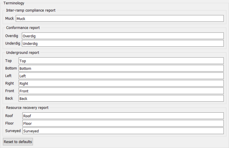
Reports
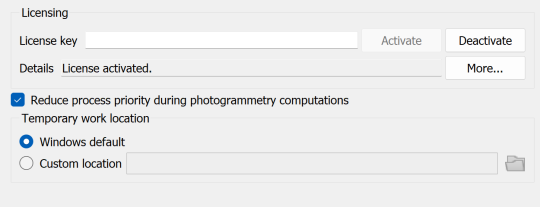
Photogrammetry
Manage Photogrammetry licensing and set processing priority.
Manage preferences
Manage preferences provides some basic housekeeping functionality such as saving, exporting and importing set-ups, as well as reset all options to default.
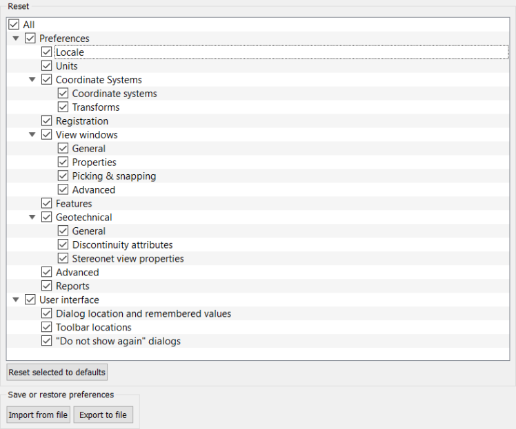
Data persistence in software extends to placement of dialogs (windows) in the workspace. Once a session is complete, the next time the software is opened, panels will appear in the same position as the previous session. This can cause a problem if, for example, two monitors were used, and a panel was placed on the second monitor. Panel positions can be reset by:
-
From the Manage preferences expand User interface options by clicking the
 expand arrow.
 -
Select Dialog location and remembered values.
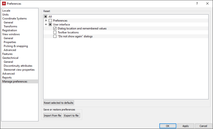
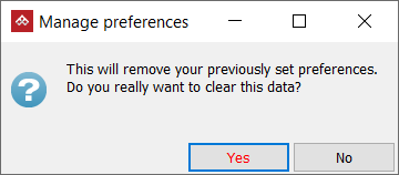
-
Click Reset selected to defaults button followed by Yes on the confirmation panel.
-
Click OK to exit the preferences options.
