Query Scanline
Source file: query-scanlines.htm
Report on discontinuities with a scanline.
The aim of the scanline is to map the discontinuities that cross a line on a rock face. A line, which can be at any angle, is drawn across the rock face. The required parameters are then detailed for each discontinuity crossing the line. This line is imagined as a straight line for input to PointModeller, much like a borehole, although an underground rock face is not planar, and the painted line follows irregularities in the face. Hence it is not millimetre perfect in practice.
Before doing a scanline query you will need to do the following:
-
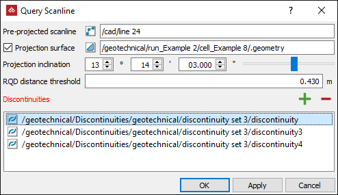
On the Geotechnical ribbon tab, go to the Scanline group and select
 Query Scanline.
 -
Select all the discontinuities on the rock face in the project explorer and click the
 button or drag them into the Discontinuities field.
Tip: Select the relevant discontinuities container to add discontinuities in bulk.
Note: The first discontinuity object or container selected will automatically appear in the Discontinuities field.
To remove a discontinuity, select it in the Discontinuities field and click the
 button.
 -
Set up the projection plane with either of the following methods:
Select the 2-point scanline in the project explorer or view window. PointModeller will display a plane through the scanline, with the plane's normal as a red arrow.
Or
Select the Projection surface checkbox. The 2-point scanline label changes to Pre-projected scanline, allowing you to use a multi-point line.
- Select a valid surface in the project explorer. The surface will automatically appear in the Projection surface field.
- Select a scanline. The scanline will appear in the Pre-projected scanline field.
PointModeller will display a plane-of-best fit to the scanline, with the plane's normal as a red arrow.
-
It's likely the plane will not be in the optimal orientation. Adjust the Projection inclination to ensure the plane captures as many of the discontinuities as possible.
-
Enter the required RQD distance threshold.
-
Click OK or Apply.
The scanline query tool will produce and display a results report containing details of each discontinuity, including intersection coordinates and distances, dip angle and direction, lengths above and below the scanline and any attributes defined in PointModeller Preferences.
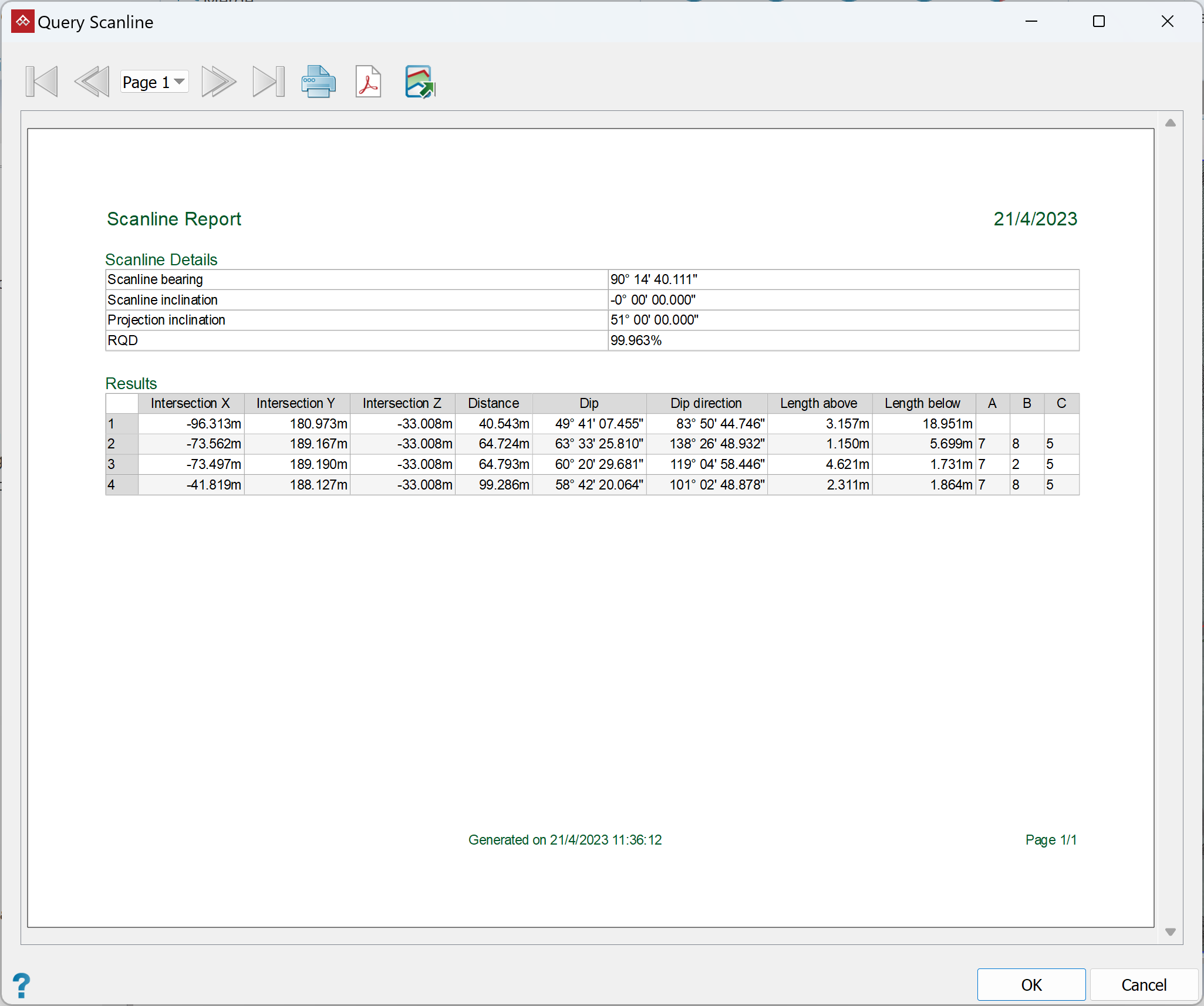
This report can be printed or saved as either a PDF or CSV file.
Results will also be saved as edge networks  called <discontinuity name> persistence, in a new container
  called Query scanline results in the scrapbook container.
